AIR CONDITIONING SYSTEM(for Manual Air Conditioning System) Air Conditioning Compressor Magnetic Clutch Circuit
DESCRIPTION
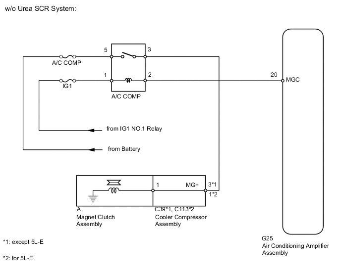
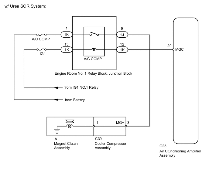
When the air conditioning amplifier assembly is turned on, a magnet clutch assembly ON signal is sent from the MGC terminal of the air conditioning amplifier assembly. Then, the A/C COMP relay turns on to operate the magnet clutch assembly.
WIRING DIAGRAM
CAUTION / NOTICE / HINT
Note
Inspect the fuses for circuits related to this system before performing the following inspection procedure.
PROCEDURE
-
CHECK VEHICLE TYPE
-
Check the vehicle type.
Result Result Proceed to w/o Urea SCR System A w/ Urea SCR System B
B 
CHECK ENGINE ROOM NO. 1 RELAY BLOCK, JUNCTION BLOCK (A/C COMP RELAY) Click here
A 
-
-
INSPECT MAGNET CLUTCH RELAY (A/C COMP)
-
Remove the A/C COMP relay from the engine room No. 1 relay block, junction block.
-
Measure the resistance according to the value(s) in the table below.
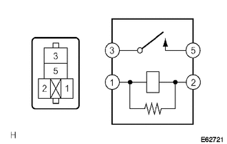
Standard Resistance Tester Connection Condition Specified Condition 3 - 5 Battery voltage is not applied to terminals 1 and 2 10 kΩ or higher Battery voltage is applied to terminals 1 and 2 Below 1 Ω
NG 
REPLACE MAGNET CLUTCH RELAY (A/C COMP)
NG
-
-
INSPECT COOLER COMPRESSOR ASSEMBLY
-
except 5L-E:
-
Remove the cooler compressor assembly (for 1GR-FE) Click here.
-
Remove the cooler compressor assembly (for 1KD-FTV) Click here.
-
Remove the cooler compressor assembly (for 2TR-FE) Click here.
-
Remove the cooler compressor assembly (for 1GD-FTV) Click here.
-
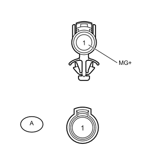
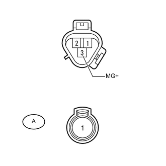
Disconnect the A magnet clutch connector.
-
Measure the resistance according to the value(s) in the table below.
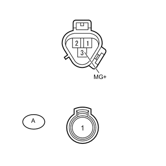
Standard Resistance Tester Connection Condition Specified Condition 3 (MG+) - A-1 Always Below 1 Ω 3 (MG+) - Body ground Always 10 kΩ or higher
-
-
for 5L-E:
-
Remove the cooler compressor assembly Click here.
-
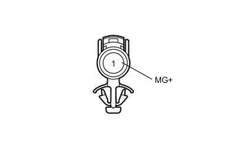
Disconnect the A magnet clutch connector.
-
Measure the resistance according to the value(s) in the table below.
Standard Resistance Tester Connection Condition Specified Condition 1 (MG+) - A-1 Always Below 1 Ω 1 (MG+) - Body ground Always 10 kΩ or higher
-
*: Replace procedure:
-
for 1GR-FE: Click here
-
for 1KD-FTV: Click here
-
for 5L-E: Click here
-
for 2TR-FE: Click here
-
for 1GD-FTV: Click here
-
-
NG
REPLACE COOLER COMPRESSOR ASSEMBLY*
NG
-
-
INSPECT MAGNET CLUTCH ASSEMBLY
-
except 5L-E:
-
Reconnect the A magnet clutch connector.
-
Apply battery voltage to the magnet clutch assembly and check the operation of the magnet clutch assembly.
OK Measurement Condition Specified Condition Battery positive (+) → Terminal 3 (MG+)
Battery negative (-) → Body ground
Magnet clutch assembly operating sound can be heard, and magnetic clutch hub and rotor lock.
-
-
for 5L-E:
-
Reconnect the A magnet clutch connector.
-
Apply battery voltage to the magnet clutch assembly and check the operation of the magnet clutch assembly.
OK Measurement Condition Specified Condition Battery positive (+) → Terminal 1 (MG+)
Battery negative (-) → Body ground
Magnet clutch assembly operating sound can be heard, and magnetic clutch hub and rotor lock.
-
*: Replace procedure:
-
for 1GR-FE: Click here
-
for 1KD-FTV: Click here
-
for 5L-E: Click here
-
for 2TR-FE: Click here
-
for 1GD-FTV: Click here
-
NG
REPLACE MAGNET CLUTCH ASSEMBLY*
OK
-
-
CHECK HARNESS AND CONNECTOR (ENGINE ROOM NO. 1 RELAY BLOCK, JUNCTION BLOCK - BATTERY)
-
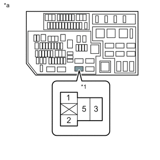
Text in Illustration *1 A/C COMP Relay *a Component without relay installed
(Engine Room No. 1 Relay Block, Junction Block)
Remove the A/C COMP relay from the engine room No. 1 relay block, junction block.
-
Measure the voltage according to the value(s) in the table below.
Standard Voltage Tester Connection Switch Condition Specified Condition A/C COMP relay terminal 1 - Body ground Ignition switch ON 11 to 14 V A/C COMP relay terminal 5 - Body ground Always 11 to 14 V
NG
REPAIR OR REPLACE HARNESS OR CONNECTOR
OK
-
-
CHECK HARNESS AND CONNECTOR (AIR CONDITIONING AMPLIFIER - BATTERY)
-
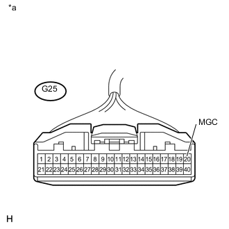
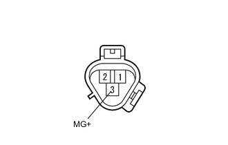
Text in Illustration *a Front view of wire harness connector
(to Air Conditioning Amplifier Assembly)
Disconnect the G25 amplifier connector.
-
Measure the voltage according to the value(s) in the table below.
Standard Voltage Tester Connection Switch Condition Specified Condition G25-20 (MGC) - Body ground Ignition switch off Below 1 V G25-20 (MGC) - Body ground Ignition switch ON 11 to 14 V
NG
REPAIR OR REPLACE HARNESS OR CONNECTOR
OK
-
-
CHECK HARNESS AND CONNECTOR (ENGINE ROOM NO. 1 RELAY BLOCK, JUNCTION BLOCK - COOLER COMPRESSOR)
-
Remove the A/C COMP relay from the engine room No. 1 relay block, junction block.
-
Disconnect the C39*1 or C113*2 compressor connector.
-
*1: except 5L-E
-
*2: for 5L-E
-
-
Measure the resistance according to the value(s) in the table below.
Standard Resistance except 5L-E Tester Connection Condition Specified Condition A/C COMP relay terminal 3 - C39-3 (MG+) Always Below 1 Ω C39-3 (MG+) - Body ground Always 10 kΩ or higher for 5L-E Tester Connection Condition Specified Condition A/C COMP relay terminal 3 - C113-1 (MG+) Always Below 1 Ω C113-1 (MG+) - Body ground Always 10 kΩ or higher
OK
PROCEED TO NEXT SUSPECTED AREA SHOWN IN PROBLEM SYMPTOMS TABLE Click here
NG
REPAIR OR REPLACE HARNESS OR CONNECTOR
-
-
CHECK ENGINE ROOM NO. 1 RELAY BLOCK, JUNCTION BLOCK (A/C COMP RELAY)
-
Remove the engine room No. 1 relay block, junction block.
-
Measure the resistance according to the value(s) in the table below.
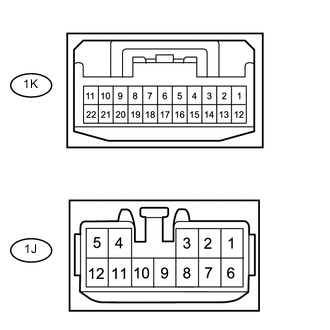
Standard Resistance Tester Connection Condition Specified Condition 1J-9 - 1K-1 Battery voltage is not applied to 1K-12 and 1K-13 10 kΩ or higher Battery voltage is applied to 1K-12 and 1K-13 Below 1 Ω
NG
REPLACE ENGINE ROOM NO. 1 RELAY BLOCK, JUNCTION BLOCK
OK
-
-
INSPECT COOLER COMPRESSOR ASSEMBLY
-
Remove the cooler compressor assembly Click here.
-
Disconnect the A magnet clutch connector.
-
Measure the resistance according to the value(s) in the table below.
Standard Resistance Tester Connection Condition Specified Condition 3 (MG+) - A-1 Always Below 1 Ω 3 (MG+) - Body ground Always 10 kΩ or higher
NG
REPLACE COOLER COMPRESSOR ASSEMBLY Click here
OK
-
-
INSPECT MAGNET CLUTCH ASSEMBLY
-
Reconnect the A magnet clutch connector.
-
Apply battery voltage to the magnet clutch assembly and check the operation of the magnet clutch assembly.
OK Measurement Condition Specified Condition Battery positive (+) → Terminal 3 (MG+)
Battery negative (-) → Body ground
Magnet clutch assembly operating sound can be heard, and magnetic clutch hub and rotor lock.
NG
REPLACE MAGNET CLUTCH ASSEMBLY Click here
OK
-
-
CHECK HARNESS AND CONNECTOR (ENGINE ROOM NO. 1 RELAY BLOCK, JUNCTION BLOCK - BATTERY)
-
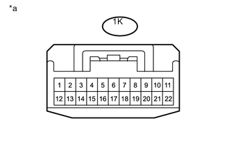
Text in Illustration *a Front view of wire harness connector
(to Engine Room No. 1 Relay Block, Junction Block)
Disconnect the 1K engine room No. 1 relay block, junction block connector.
-
Measure the voltage according to the value(s) in the table below.
Standard Voltage Tester Connection Condition Specified Condition 1K-1 - Body ground Ignition switch ON 11 to 14 V 1K-13 - Body ground Always 11 to 14 V
NG
REPAIR OR REPLACE HARNESS OR CONNECTOR
OK
-
-
CHECK HARNESS AND CONNECTOR (AIR CONDITIONING AMPLIFIER - BATTERY)
-
Text in Illustration *a Front view of wire harness connector
(to Air Conditioning Amplifier Assembly)
Disconnect the G25 amplifier connector.
-
Measure the voltage according to the value(s) in the table below.
Standard Voltage Tester Connection Switch Condition Specified Condition G25-20 (MGC) - Body ground Ignition switch off Below 1 V G25-20 (MGC) - Body ground Ignition switch ON 11 to 14 V
NG
REPAIR OR REPLACE HARNESS OR CONNECTOR
OK
-
-
CHECK HARNESS AND CONNECTOR (ENGINE ROOM NO. 1 RELAY BLOCK, JUNCTION BLOCK - COOLER COMPRESSOR)
-
Disconnect the 1J engine room No. 1 relay block, junction block connector.
-
Disconnect the C39 cooler compressor assembly connector.
-
Measure the resistance according to the value(s) in the table below.
Standard Resistance Tester Connection Condition Specified Condition 1J-9 - C39-3 (MG+) Always Below 1 Ω C39-3 (MG+) - Body ground Always 10 kΩ or higher
OK
PROCEED TO NEXT SUSPECTED AREA SHOWN IN PROBLEM SYMPTOMS TABLE Click here
NG
REPAIR OR REPLACE HARNESS OR CONNECTOR
-