AIR CONDITIONING SYSTEM(for Manual Air Conditioning System) Viscous Heater with Magnet Clutch Circuit
DESCRIPTION
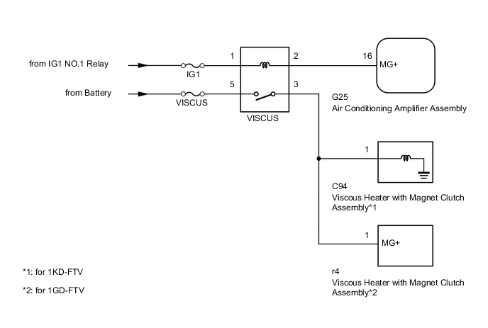
When the idle up switch assembly is pushed, the air conditioning amplifier assembly turns on the viscous heater relay and operates the viscous heater. If the viscous heater does not operate when the idle up switch assembly is pushed, there may be a problem in the circuit shown below.
WIRING DIAGRAM
CAUTION / NOTICE / HINT
Note
Inspect the fuses for circuits related to this system before performing the following inspection procedure.
PROCEDURE
-
PERFORM ACTIVE TEST USING GTS (VISCOUS HEATER)
-
Select the Active Test, use the GTS to generate a control command, and then check that the viscous heater with magnet clutch assembly operates Click here.
Air Conditioner Tester Display Test Part Control Range Diagnostic Note Viscous Heater Viscous heater with magnet clutch assembly operation ON or OFF - OK The display is as specified in the normal condition column.
OK 
PROCEED TO NEXT SUSPECTED AREA SHOWN IN PROBLEM SYMPTOMS TABLE Click here
NG 
-
-
CHECK HARNESS AND CONNECTOR (ENGINE ROOM NO. 1 RELAY BLOCK, JUNCTION BLOCK - BATTERY)
-
except 1GD-FTV, w/ Urea SCR System:
-
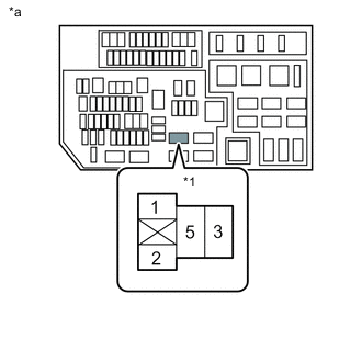
Text in Illustration *1 VISCUS Relay *a Component without relay installed
(Engine Room No. 1 Relay Block, Junction Block)
Remove the viscous heater relay (VISCUS) from the engine room No. 1 relay block, junction block.
-
Measure the voltage according to the value(s) in the table below.
Standard Voltage Tester Connection Condition Specified Condition VISCUS relay terminal 5 - Body ground Ignition switch ON 11 to 14 V VISCUS relay terminal 2 - Body ground Always 11 to 14 V
-
-
for 1GD-FTV, w/ Urea SCR System:
-
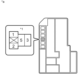
Text in Illustration *1 Viscous heater Relay (VISCUS) *a Component without relay installed
(Engine Room No. 1 Relay Block, Junction Block)
Remove the viscous heater relay (VISCUS) from the engine room No. 1 relay block, junction block.
-
Measure the voltage according to the value(s) in the table below.
Standard Voltage Tester Connection Condition Specified Condition VISCUS relay terminal 5 - Body ground Ignition switch ON 11 to 14 V VISCUS relay terminal 2 - Body ground Always 11 to 14 V
-
NG
REPAIR OR REPLACE HARNESS OR CONNECTOR
OK
-
-
INSPECT VISCOUS HEATER RELAY (VISCUS)
-
Remove the viscous heater relay (VISCUS) from engine room No. 1 relay block, junction block.
-
Inspect the viscous heater relay (VISCUS) Click here.
Result Result Proceed to OK (for 1KD-FTV) A OK (for 1GD-FTV) B NG C
B 
CHECK HARNESS AND CONNECTOR (ENGINE ROOM NO. 1 RELAY BLOCK, JUNCTION BLOCK - VISCOUS HEATER WITH MAGNET CLUTCH ASSEMBLY) Click here
C
REPLACE VISCOUS HEATER RELAY (VISCUS)
A
-
-
CHECK HARNESS AND CONNECTOR (ENGINE ROOM NO. 1 RELAY BLOCK, JUNCTION BLOCK - VISCOUS HEATER WITH MAGNET CLUTCH ASSEMBLY)
-
Remove the viscous heater relay (VISCUS) from the engine room No. 1 relay block, junction block.
-
Disconnect the C94 viscous heater with magnet clutch assembly connector.
-
Measure the resistance according to the value(s) in the table below.
Standard Resistance Tester Connection Condition Specified Condition Viscous heater relay (VISCUS) terminal 3 - C94-1 Always Below 1 Ω Viscous heater relay (VISCUS) terminal 3 - Body ground Always 10 kΩ or higher
NG
REPAIR OR REPLACE HARNESS OR CONNECTOR
OK
-
-
CHECK HARNESS AND CONNECTOR (ENGINE ROOM NO. 1 RELAY BLOCK, JUNCTION BLOCK - AIR CONDITIONING AMPLIFIER ASSEMBLY)
-
Remove the viscous heater relay (VISCUS) from the engine room No. 1 relay block, junction block.
-
Disconnect the G25 air conditioning amplifier assembly connector.
-
Measure the resistance according to the value(s) in the table below.
Standard Resistance Tester Connection Condition Specified Condition Viscous heater relay (VISCUS) terminal 2 - G25-16 (MG+) Always Below 1 Ω Viscous heater relay (VISCUS) terminal 2 - Body ground Always 10 kΩ or higher
NG
REPAIR OR REPLACE HARNESS OR CONNECTOR
OK
-
-
INSPECT VISCOUS HEATER WITH MAGNET CLUTCH ASSEMBLY
-
Remove the viscous heater with magnet clutch assembly Click here.
-
Inspect the viscous heater with magnet clutch assembly Click here.
OK
REPLACE AIR CONDITIONING AMPLIFIER ASSEMBLY Click here
NG
REPLACE VISCOUS HEATER WITH MAGNET CLUTCH ASSEMBLY Click here
-
-
CHECK HARNESS AND CONNECTOR (ENGINE ROOM NO. 1 RELAY BLOCK, JUNCTION BLOCK - VISCOUS HEATER WITH MAGNET CLUTCH ASSEMBLY)
-
Remove the viscous heater relay (VISCUS) from the engine room No. 1 relay block, junction block.
-
Disconnect the r4 viscous heater with magnet clutch assembly connector.
-
Measure the resistance according to the value(s) in the table below.
Standard Resistance Tester Connection Condition Specified Condition Viscous heater relay (VISCUS) terminal 3 - r4-1 Always Below 1 Ω Viscous heater relay (VISCUS) terminal 3 - Body ground Always 10 kΩ or higher
NG
REPAIR OR REPLACE HARNESS OR CONNECTOR
OK
-
-
CHECK HARNESS AND CONNECTOR (ENGINE ROOM NO. 1 RELAY BLOCK, JUNCTION BLOCK - AIR CONDITIONING AMPLIFIER ASSEMBLY)
-
Remove the viscous heater relay (VISCUS) from the engine room No. 1 relay block, junction block.
-
Disconnect the G25 air conditioning amplifier assembly connector.
-
Measure the resistance according to the value(s) in the table below.
Standard Resistance Tester Connection Condition Specified Condition Viscous heater relay (VISCUS) terminal 2 - G25-16 (MG+) Always Below 1 Ω Viscous heater relay (VISCUS) terminal 2 - Body ground Always 10 kΩ or higher
NG
REPAIR OR REPLACE HARNESS OR CONNECTOR
OK
-
-
INSPECT VISCOUS HEATER WITH MAGNET CLUTCH ASSEMBLY
-
Remove the viscous heater with magnet clutch assembly Click here.
-
Inspect the viscous heater with magnet clutch assembly Click here.
OK
REPLACE AIR CONDITIONING AMPLIFIER ASSEMBLY Click here
NG
REPLACE VISCOUS HEATER WITH MAGNET CLUTCH ASSEMBLY Click here
-