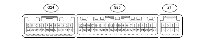
COMBUSTION TYPE POWER HEATER SYSTEM TERMINALS OF ECU
-
CHECK HEATER ASSEMBLY

-
Measure the voltage, resistance and waveform according to the value(s) in the table below.
Terminal No. (Symbol) Wiring Color Terminal Description Condition Specified Condition A97-1 (E) - Body ground W-B - Body ground Ground for main power supply Always Below 1 Ω A97-2 (L) - Body ground R - Body ground Heater pump operation signal Engine idling
Power heater switch on
Pulse generation
(See waveform 1)
A97-3 (IG) - Body ground W - Body ground Power heater operating signal Engine switch on (IG)
Power heater switch on
11 to 14 V Engine switch on (IG)
Power heater switch off
Below 1 V A97-5 (B) - Body ground B - Body ground Power source Always 11 to 14 V A97-8 (+) - Body ground G - Body ground Engine operating signal Engine idling 11 to 14 V -
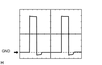
Using an oscilloscope, check waveform 1.
Heater Pump Control Signal Item Content Terminal No. (Symbol) A97-2 (L) - Body ground Tool Setting 2 V/DIV., 20 ms/DIV. Condition Engine idling
Power heater switch on
-
-
CHECK AIR CONDITIONING AMPLIFIER ASSEMBLY
-
Measure the voltage according to the value(s) in the table below.
Terminal No. (Symbol) Wiring Color Terminal Description Condition Specified Condition G25-18 (HTR1) - G25-14 (GND) G - W-B Engine operating signal Engine idling 11 to 14 V
-