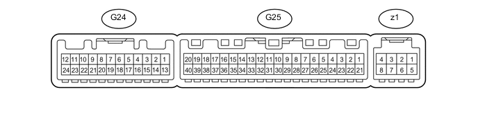
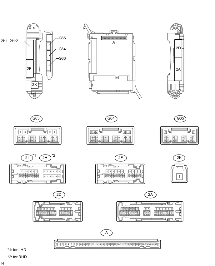
AIR CONDITIONING SYSTEM(for Automatic Air Conditioning System) TERMINALS OF ECU
-
CHECK AIR CONDITIONING AMPLIFIER ASSEMBLY
-
Disconnect the G24 and G25 amplifier connectors.
-
Measure the voltage and resistance according to the value(s) in the table below.
Terminal No. (Symbol) Wiring Color Terminal Description Condition Specified Condition G25-21 (B) - G25-14 (GND) V - W-B Battery power source Always 11 to 14 V G25-1 (IG+) - G25-14 (GND) L - W-B Ignition power supply Ignition switch ON 11 to 14 V Ignition switch off Below 1 V G25-14 (GND) - Body ground W-B - Body ground Ground for main power supply Always Below 1 Ω G24-20 (RGND) - Body ground W-B - Body ground Ground for main power supply Always Below 1 Ω G24-24 (+B2) - G24-20 (RGND) GR - W-B Battery power source Always 11 to 14 V -
Reconnect the G24 and G25 amplifier connectors.
-
Measure the voltage and waveform according to the value(s) in the table below.
Terminal No. (Symbol) Wiring Color Terminal Description Condition Specified Condition G25-3 (PTC1) - Body ground*2 V - Body ground PTC NO.1 relay operation signal*10
PTC HTR NO.1 relay operation signal*11
-
Engine running (1250 rpm or more)
-
Temperature setting MAX HOT
-
Outside temperature 10°C (50°F) or less
-
Engine coolant temperature 79°C (175°F) or less
-
Headlight dimmer switch off
-
Blower switch off → on
11 to 14 V → Below 1 V G25-4 (PTC3) - Body ground*2 P - Body ground PTC NO.3 relay operation signal*10
PTC HTR NO.3 relay operation signal*11
-
Engine running (1250 rpm or more)
-
Temperature setting MAX HOT
-
Outside temperature 10°C (50°F) or less
-
Engine coolant temperature 73°C (163°F) or less
-
Headlight dimmer switch off
-
Blower switch off → on
11 to 14 V → Below 1 V G25-5 (TAM) - G25-13 (SG-2) V - G Cooler thermistor (ambient temperature sensor) signal
-
Ignition switch ON
-
Ambient temperature 25°C (77°F)
1.35 to 1.75 V G25-5 (TAM) - G25-13 (SG-2) V - G Cooler thermistor (ambient temperature sensor) signal
-
Ignition switch ON
-
Ambient temperature 40°C (104°F)
0.9 to 1.2 V G25-8 (LOCK) - G25-13 (SG-2) R - G A/C compressor lock sensor signal
-
Engine running
-
Blower switch LO
-
A/C switch on (magnet clutch on)
Pulse generation
(See waveform 1)
G25-9 (PRE) - G25-13 (SG-2)*3 G - G Air conditioner pressure sensor signal
-
Ignition switch ON
-
Refrigerant pressure normal (below 3.025 MPa [30.9 kgf/cm2, 438.6 psi] and higher than 0.176 MPa [1.8 kgf/cm2, 25.5 psi])
0.63 to 4.72 V G25-9 (PRE) - G25-13 (SG-2)*3 G - G Air conditioner pressure sensor signal
-
Ignition switch ON
-
Refrigerant pressure abnormal (below 0.176 MPa [1.8 kgf/cm2, 25.5 psi])
Below 0.63 V G25-9 (PRE) - G25-13 (SG-2)*3 G - G Air conditioner pressure sensor signal
-
Ignition switch ON
-
Refrigerant pressure abnormal (higher than 3.025 MPa [30.9 kgf/cm2, 438.6 psi])
4.72 V or higher G25-9 (PRE) - Body ground*4 G - Body ground No. 1 pressure switch signal
-
Ignition switch ON
-
Refrigerant pressure normal (below 3.14 MPa [32.0 kgf/cm2, 455 psi] and higher than 0.196 MPa [2.0 kgf/cm2, 28 psi])
Below 1 V G25-9 (PRE) - Body ground*4 G - Body ground No. 1 pressure switch signal
-
Ignition switch ON
-
Refrigerant pressure abnormal (below 0.196 MPa [2.0 kgf/cm2, 28 psi] or higher than 3.14 MPa [32.0 kgf/cm2, 455 psi])
4.69 V or higher G25-10 (S5-3) - G25-13 (SG-2) B - G Power supply for air conditioner pressure sensor Ignition switch ON 4.75 to 5.25 V G25-15 (COOL) - G25-14 (GND)*5 V - W-B Cooling box assembly operation signal
-
Engine running
-
Cooler control switch sub-assembly on
Below 1 V G25-16 (MG+) - G25-14 (GND)*6 V - W-B Viscous with magnetic clutch heater assembly operation signal
-
Engine running
-
Power heater switch on
Below 1 V G25-17 (AC1) - G25-14 (GND) LG - W-B Compressor operation signal
-
Engine running
-
Blower switch LO
-
A/C switch off
11 to 14 V
-
Engine running
-
Blower switch LO
-
A/C switch on
Below 1 V G25-18 (HTR1) - G25-14 (GND)*12 G - W-B Engine operating signal Engine idling 11 to 14 V G25-20 (MGC) - G25-14 (GND) R - W-B Magnet clutch assembly operation signal
-
Engine running
-
A/C switch off → on
-
Blower switch LO
-
Magnet clutch assembly off → on
11 to 14 V → Below 1 V G25-22 (PTC2) - Body ground*2 LG - Body ground PTC NO.2 relay operation signal*10
PTC HTR NO.2 relay operation signal*11
-
Engine running (1250 rpm or more)
-
Temperature setting MAX HOT
-
Outside temperature 10°C (50°F) or less
-
Engine coolant temperature 76°C (169°F) or less
-
Headlight dimmer switch off
-
Blower switch off → on
11 to 14 V → Below 1 V G25-23 (BLW) - G25-14 (GND) L - W-B Blower with fan motor sub-assembly control signal
-
Ignition switch ON
-
Blower switch LO
Pulse generation
(See waveform 2)
G25-25 (ALT) - G25-14 (GND)*13 L - W-B Generator signal (PTC heater control) Engine started Pulse generation G25-27 (ACT) - G25-14 (GND) R - W-B Compressor operation signal
-
Engine running
-
Blower switch LO
-
A/C switch off (magnet clutch off)
Below 1 V
-
Engine running
-
Blower switch LO
-
A/C switch on (magnet clutch on)
4.75 to 5.25 V G25-29 (TR) - G25-34 (SG-1) GR - P Cooler thermistor (room temperature sensor) signal
-
Ignition switch ON
-
Cabin temperature at 25°C (77°F)
1.8 to 2.2 V
-
Ignition switch ON
-
Cabin temperature at 40°C (104°F)
1.2 to 1.6 V G25-32 (TSP) - G25-14 (GND) V - W-B*8
G - W-B*9
Automatic light control sensor (solar sensor) power signal (for front passenger side)
-
Ignition switch ON
-
Solar sensor subjected to electric light
-
Vehicle indoors
0.8 to 4.3 V
-
Ignition switch ON
-
Automatic light control sensor (solar sensor) covered with cloth
-
Vehicle indoors
Below 0.8 V G25-33 (TSD) - G25-14 (GND) G - W-B*8
V - W-B*9
Automatic light control sensor (solar sensor) power signal (for driver side)
-
Ignition switch ON
-
Solar sensor subjected to electric light
-
Vehicle indoors
0.8 to 4.3 V
-
Ignition switch ON
-
Automatic light control sensor (solar sensor) covered with cloth
-
Vehicle indoors
Below 0.8 V G25-36 (SWVC) - G25-14 (GND)*6, *7 W - W-B
-
Heater switch assembly operation signal*6
-
Idle up switch operation signal*7
-
Engine running
-
A/C switch on
-
Heater switch assembly on*5
-
Idle up switch on*6
Below 1 V G25-37 (LIN1) - Body ground P - Body ground LIN communication signal Ignition switch ON Pulse generation G24-1 (RBUS) - G24-21 (RBUG)*1 LG - L BUS IC control signal (for Rear) Ignition switch ON Pulse generation G24-4 (TEC) - G24-19 (SGND)*1 SB - V Rear evaporator temperature sensor signal
-
Ignition switch ON
-
Rear evaporator temperature 0°C (32°F)
2.0 to 2.4 V
-
Ignition switch ON
-
Rear evaporator temperature 15°C (59°F)
1.4 to 1.8 V G24-7 (SG-6) - Body ground*1 R - Body ground Ground for cooler thermistor (rear room temperature sensor) Always Below 1 V G24-12 (SWCB) - G25-14 (GND)*5 LG - W-B Cooling box assembly operation signal
-
Engine running
-
A/C switch on
-
Cooler control switch sub-assembly on
Below 1 V G24-13 (RLIN) - Body ground*1 L - Body ground LIN communication signal Ignition switch ON Pulse generation G24-17 (TR) - G24-7 (SG-6)*1 B - R Cooler thermistor (rear room temperature sensor) signal
-
Ignition switch ON
-
Cabin temperature 25°C (77°F)
1.8 to 2.2 V
-
Ignition switch ON
-
Cabin temperature 40°C (104°F)
1.2 to 1.6 V G24-19 (SGND) - Body ground*1 V - Body ground Ground for rear evaporator temperature sensor Always Below 1 V G24-22 (BLWH) - G24-20 (RGND)*1 W - W-B Rear blower with fan motor sub-assembly control signal
-
Ignition switch ON
-
Rear blower switch on
Pulse generation
(See waveform 3)
G24-23 (RBBU) - G24-21 (RBUG)*1 P - L Power supply for BUS IC (for Rear) Always 11 to 14 V z1-2 (BUS G) - Body ground - Ground for BUS IC Always Below 1 V z1-3 (BUS) - z1-2 (BUS G) - BUS IC control signal Ignition switch ON Pulse generation z1-4 (B BUS) - z1-2 (BUS G) - Power supply for BUS IC Always 11 to 14 V z1-6 (TEA) - z1-5 (SGA) - No. 1 cooler thermistor signal
-
Ignition switch ON
-
Evaporator temperature 0°C (32°F)
1.7 to 2.1 V
-
Ignition switch ON
-
Evaporator temperature 15°C (59°F)
0.9 to 1.3 V
-
*1: w/ Rear Air Conditioning System
-
*2: w/ PTC Heater
-
*3: for Sensor Type
-
*4: for Switch Type
-
*5: w/ Refrigerated Cool Box
-
*6: w/ Viscous Heater
-
*7: w/ Idle Up Switch
-
*8: for LHD
-
*9: for RHD
-
*10: w/o Urea SCR System
-
*11: w/ Urea SCR System
-
*12: w/ Combustion Type Power Heater System
-
*13: w/ PTC Heater (for 1GR-FE or 1KD-FTV)
-
-
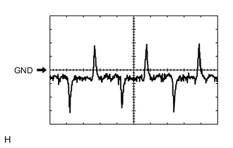
Using an oscilloscope, check waveform 1.
A/C Compressor Lock Sensor Signal Item Content Terminal No. (Symbol) G25-8 (LOCK) - G25-13 (SG-2) Tool Setting 200 mV/DIV., 10 ms./DIV. Condition
-
Engine running
-
Blower switch LO
-
A/C switch on (magnet clutch on)
-
-
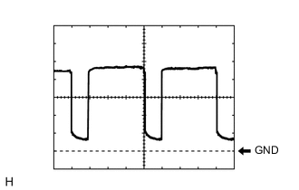
Using an oscilloscope, check waveform 2.
Blower Motor Control Signal Item Content Terminal No. (Symbol) G25-23 (BLW) - G25-14 (GND) Tool Setting 1 V/DIV., 500 μs/DIV. Condition
-
Ignition switch ON
-
Blower switch LO
Tech Tips
When the blower level is increased, the duty ratio changes accordingly.
-
-
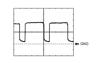
Using an oscilloscope, check waveform 3.
Blower Motor Control Signal Item Content Terminal No. (Symbol) G24-22 (BLWH) - G24-20 (RGND) Tool Setting 2 V/DIV., 500 μs/DIV. Condition
-
Ignition switch ON
-
Blower switch LO
Tech Tips
When the blower level is increased, the duty ratio changes accordingly.
-
-
-
CHECK AIR CONDITIONING AMPLIFIER ASSEMBLY (FOR COOLING BOX) (w/ Refrigerated Cool Box)

-
Disconnect the air conditioning amplifier (for cooling box) connector.
-
Measure the voltage according to the value(s) in the table below.
Terminal No. (Symbol) Wiring Color Terminal Description Condition Specified Condition 1 (+B) - 4 (GND) W-R - W-B Battery power source Always 11 to 14 V 2 (IG+) - 4 (GND) GR - W-B IG power supply Ignition switch ON 11 to 14 V -
Reconnect the air conditioning amplifier (for cooling box) connector.
-
Measure the resistance and voltage according to the value(s) in the table below.
Terminal No. (Symbol) Wiring Color Terminal Description Condition Specified Condition 5 (SW) - 4 (GND) LG-R - W-B Cooler control switch sub-assembly operation signal
-
Engine running
-
Cooler control switch sub-assembly on
Below 1 V 6 (CBI) - 4 (GND) L-G - W-B Cooler compressor permission signal
-
Engine running
-
Cooler control switch sub-assembly on
Below 1 V 7 (LED) - 4 (GND) L-B - W-B Cooling box indicator signal
-
Engine running
-
Cooler control switch sub-assembly on
Below 1 V 8 (CBT) - 4 (GND) BR-Y - W-B Air conditioning amplifier assembly request signal
-
Engine running
-
Cooler control switch sub-assembly on
Below 1 V 9 (BLW) - 4 (GND) W - W-B No. 1 cooler blower motor sub-assembly operation signal
-
Engine running
-
Cooler control switch sub-assembly on
Below 1 V 10 (SG) - 4 (GND) W-L - W-B Ground Always Below 1 Ω -
-
-
CHECK INTEGRATION CONTROL AND PANEL ASSEMBLY

-
Disconnect the G23 panel connector.
-
Measure the resistance and voltage according to the value(s) in the table below.
Terminal No. (Symbol) Wiring Color Terminal Description Condition Specified Condition G23-1 (+B) - G23-4 (GND) L - W-B Battery power source Always 11 to 14 V G23-5 (IG) - G23-4 (GND) L - W-B IG power supply Ignition switch ON 11 to 14 V Ignition switch off Below 1 V G23-6 (ACC) - G23-4 (GND) P - W-B ACC power supply Ignition switch ACC 11 to 14 V Ignition switch off Below 1 V G23-4 (GND) - Body ground W-B - Body ground Ground Always Below 1 Ω -
Reconnect the G23 panel connector.
-
Measure the waveform according to the value(s) in the table below.
Terminal No. (Symbol) Wiring Color Terminal Description Switch Condition Specified Condition G23-3 (LIN1) - Body ground P - Body ground LIN communication signal Ignition switch ON Pulse generation
-
-
CHECK AIR CONDITIONING CONTROL ASSEMBLY (w/ Rear Air Conditioning System, w/o Rear Seat Heater)

-
Disconnect the T3 control connector.
-
Measure the resistance and voltage according to the value(s) in the table below.
Terminal No. (Symbol) Wiring Color Terminal Description Condition Specified Condition T3-5 (IG) - T3-8 (E) L - W-B IG power supply Ignition switch ON 11 to 14 V Ignition switch off Below 1 V T3-8 (E) - Body ground W-B - Body ground Ground Always Below 1 Ω -
Reconnect the T3 control connector.
-
Measure the waveform according to the value(s) in the table below.
Terminal No. (Symbol) Wiring Color Terminal Description Switch Condition Specified Condition T3-3 (RLIN) - Body ground L - Body ground LIN communication signal Ignition switch ON Pulse generation
-
-
CHECK AIR CONDITIONING CONTROL ASSEMBLY (w/ Rear Air Conditioning System, w/ Rear Seat Heater)

-
Disconnect the T7 control connector.
-
Measure the resistance and voltage according to the value(s) in the table below.
Terminal No. (Symbol) Wiring Color Terminal Description Condition Specified Condition T7-1 (IG) - T7-8 (E) L - W-B IG power supply Ignition switch ON 11 to 14 V Ignition switch off Below 1 V T7-8 (E) - Body ground W-B - Body ground Ground Always Below 1 Ω -
Reconnect the T7 control connector.
-
Measure the waveform according to the value(s) in the table below.
Terminal No. (Symbol) Wiring Color Terminal Description Switch Condition Specified Condition T7-6 (RLIN) - Body ground L - Body ground LIN communication signal Ignition switch ON Pulse generation
-
-
CHECK DRIVER SIDE JUNCTION BLOCK ASSEMBLY AND MAIN BODY ECU (MULTIPLEX NETWORK BODY ECU)
-
Remove the main body ECU Click here.
-
Measure the voltage and resistance according to the value(s) in the table below.
Terminal No. (Symbol) Wiring Color Terminal Description Condition Specified Condition A-11 (GND1) - Body ground - Ground Always Below 1 Ω A-29 (ACC) - Body ground - ACC power supply Ignition switch ACC 11 to 14 V Ignition switch off Below 1 V A-31 (ALTB) - Body ground - Battery power supply Always 11 to 14 V A-32 (IG) - Body ground - Ignition switch power supply Ignition switch ON 11 to 14 V Ignition switch off Below 1 V -
Install the main body ECU Click here.
-
Measure the voltage and resistance according to the value(s) in the table below.
Terminal No. (Symbol) Wiring Color Terminal Description Condition Specified Condition G64-20 (CLTB) - Body ground P - Body ground Automatic light control sensor power supply output Ignition switch off Below 1 V Ignition switch ON 11 to 14 V G64-22 (CLTE) - Body ground L - Body ground Automatic light control sensor ground Always Below 1 Ω
-