AIR CONDITIONING SYSTEM(for Automatic Air Conditioning System) ECO Switch Circuit
DESCRIPTION
When the ECO mode switch is turned on, the air conditioning amplifier assembly receives an ECO mode switch ON signal and controls the air conditioning to enhance fuel efficiency.
WIRING DIAGRAM
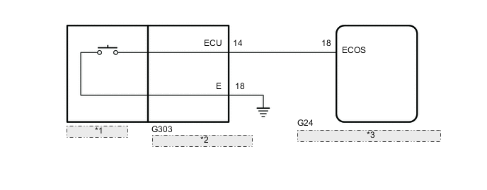
| *1 | ECO Mode Switch |
| *2 | Shift Position Indicator |
| *3 | Air Conditioning Amplifier Assembly |
PROCEDURE
-
READ VALUE USING GTS
-
Connect the GTS to the DLC3.
-
Turn the engine switch on (IG).
-
Turn the GTS on.
-
Enter the following menus: Body Electrical / Air Conditioner / Data List.
-
Read the Data List according to the display on the GTS.
Tester Display Measurement Item/Range Normal Condition Diagnostic Note ECO Switch ECO mode switch / ON or OFF ON: ECO mode switch on
OFF: ECO mode switch off
- OK Combination switch assembly (ECO mode switch) condition displayed on the GTS changes with the actual switch operation. Result Proceed to OK NG
OK 
PROCEED TO NEXT SUSPECTED AREA SHOWN IN PROBLEM SYMPTOMS TABLE Click here
NG 
-
-
INSPECT ECO MODE SWITCH
-
Remove the ECO mode switch.
-
Inspect the ECO mode switch.
Result Proceed to OK NG
NG
REPLACE ECO MODE SWITCH Click here
OK
-
-
CHECK HARNESS AND CONNECTOR (SHIFT POSITION INDICATOR - AIR CONDITIONING AMPLIFIER ASSEMBLY AND BODY GROUND)
-
Disconnect the G24 air conditioning amplifier assembly connector.
-
Disconnect the G303 shift position indicator connector.
-
Measure the resistance according to the value(s) in the table below.
Standard Resistance Tester Connection Condition Specified Condition G303-14 (ECU) - G24-18 (ECOS) Always Below 1 Ω G303-18 (E) - Body ground Always Below 1 Ω G303-14 (ECU) or G24-18 (ECOS) - Body ground Always 10 kΩ or higher Result Proceed to OK NG
NG
REPAIR OR REPLACE HARNESS OR CONNECTOR
OK
-
-
CHECK SHIFT POSITION INDICATOR
-
Replace the shift position indicator with a known good one Click here.
-
Check that the malfunction disappears.
OK Malfunction disappears. Result Proceed to OK NG
OK
END (SHIFT POSITION INDICATOR WAS DEFECTIVE)
NG
REPLACE AIR CONDITIONING AMPLIFIER ASSEMBLY Click here
-