REAR POWER SEAT CONTROL SYSTEM Rear Power Seat Switch Circuit
DESCRIPTION
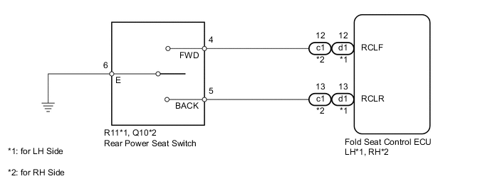
When the rear power seat switch is operated, a recline signal is sent to the fold seat control ECU. The ECU activates the power seat motor based on the signal from the rear power seat switch.
WIRING DIAGRAM
PROCEDURE
-
CHECK FOLD SEAT CONTROL ECU
-
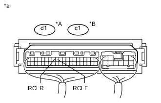
Text in Illustration *A for LH Side *B for RH Side *a Component with harness connected
(Fold Seat Control ECU)
Remove the fold seat control ECU with its connectors still connected Click here.
-
Measure the voltage according to the value(s) in the table below.
Standard Voltage for LH side Tester Connection Condition Specified Condition d1-12 (RCLF) - Body ground Always 11 to 14 V Rear power seat switch LH forward Below 1 V d1-13 (RCLR) - Body ground Always 11 to 14 V Rear power seat switch LH backward Below 1 V RH side Tester Connection Condition Specified Condition c1-12 (RCLF) - Body ground Always 11 to 14 V Rear power seat switch RH forward Below 1 V c1-13 (RCLR) - Body ground Always 11 to 14 V Rear power seat switch RH backward Below 1 V
OK 
PROCEED TO NEXT SUSPECTED AREA SHOWN IN PROBLEM SYMPTOMS TABLE Click here
NG 
-
-
INSPECT REAR POWER SEAT SWITCH
-
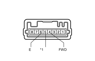
*1 BACK Remove the rear power seat switch Click here.
-
Measure the resistance according to the value(s) in the table below.
Standard Resistance Tester Connection Condition Specified Condition 4 (FWD) - 6 (E) Always 10 kΩ or higher Rear power seat switch forward Below 1 Ω 5 (BACK) - 6 (E) Always 10 kΩ or higher Rear power seat switch backward Below 1 Ω
NG
REPLACE REAR POWER SEAT SWITCH Click here
OK
-
-
CHECK HARNESS AND CONNECTOR (FOLD SEAT CONTROL ECU - REAR POWER SEAT SWITCH)
-
*1: for LH Side
-
*2: for RH Side
-
Disconnect the d1*1 or c1*2 ECU connector.
-
Disconnect the R11*1 or Q10*2 switch connector.
-
Measure the resistance according to the value(s) in the table below.
Standard Resistance for LH Side Tester Connection Condition Specified Condition d1-12 (RCLF) - R11-4 (FWD) Always Below 1 Ω d1-12 (RCLF) - Body ground Always 10 kΩ or higher d1-13 (RCLR) - R11-5 (BACK) Always Below 1 Ω d1-13 (RCLR) - Body ground Always 10 kΩ or higher for RH Side Tester Connection Condition Specified Condition c1-12 (RCLF) - Q10-4 (FWD) Always Below 1 Ω c1-12 (RCLF) - Body ground Always 10 kΩ or higher c1-13 (RCLR) - Q10-5 (BACK) Always Below 1 Ω c1-13 (RCLR) - Body ground Always 10 kΩ or higher
OK
REPLACE FOLD SEAT CONTROL ECU Click here
NG
REPAIR OR REPLACE HARNESS OR CONNECTOR
-