REAR POWER SEAT CONTROL SYSTEM Power Source Circuit
DESCRIPTION
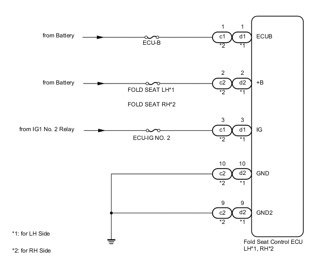
Power is supplied to the fold seat control ECU through the ECU-B, FOLD SEAT LH*1, FOLD SEAT RH*2 and ECU-IG NO. 2 fuses.
-
*1: for LH Side
-
*2: for RH Side
WIRING DIAGRAM
CAUTION / NOTICE / HINT
Tech Tips
Inspect the fuses for circuits related to this system before performing the following inspection procedure.
PROCEDURE
-
CHECK HARNESS AND CONNECTOR (FOLD SEAT CONTROL ECU - BATTERY AND BODY GROUND)
-
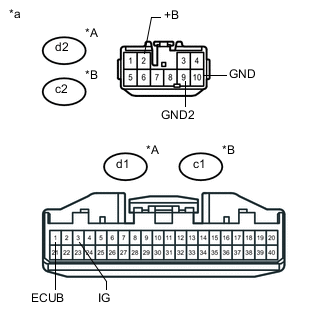
Text in Illustration *A for LHD *B for RHD *a Front view of wire harness connector
(to Fold Seat Control ECU)
for LH Side:
Disconnect the d1 and d2 ECU connectors.
-
for RH Side:
Disconnect the c1 and c2 ECU connectors.
-
Measure the voltage according to the value(s) in the table below.
Standard Voltage for LH Side Tester Connection Condition Specified Condition d2-2 (+B) - Body ground Always 11 to 14 V d1-1 (ECUB) - Body ground Always 11 to 14 V d1-3 (IG) - Body ground Ignition switch off Below 1 V Ignition switch ON 11 to 14 V for RH Side Tester Connection Condition Specified Condition c2-2 (+B) - Body ground Always 11 to 14 V c1-1 (ECUB) - Body ground Always 11 to 14 V c1-3 (IG) - Body ground Ignition switch off Below 1 V Ignition switch ON 11 to 14 V -
Measure the resistance according to the value(s) in the table below.
Standard Resistance for LH Side Tester Connection Condition Specified Condition d2-10 (GND) - Body ground Always Below 1 Ω d2-9 (GND2) - Body ground Always Below 1 Ω for RH Side Tester Connection Condition Specified Condition c2-10 (GND) - Body ground Always Below 1 Ω c2-9 (GND2) - Body ground Always Below 1 Ω
OK 
PROCEED TO NEXT SUSPECTED AREA SHOWN IN PROBLEM SYMPTOMS TABLE Click here
NG
REPAIR OR REPLACE HARNESS OR CONNECTOR
-