REAR POWER SEAT CONTROL SYSTEM Parking Brake Switch Circuit
DESCRIPTION
This circuit includes the parking brake switch assembly and fold seat control ECU.
WIRING DIAGRAM

PROCEDURE
-
CHECK BRAKE WARNING LIGHT
-
Check that the brake warning light comes on when the parking brake is applied and goes off when the parking brake is released.
OK The brake warning light operates as specified above.
NG 
INSPECT PARKING BRAKE SWITCH ASSEMBLY Click here
OK 
-
-
CHECK HARNESS AND CONNECTOR (FOLD SEAT CONTROL ECU - PARKING BRAKE SWITCH)
-
Disconnect the d1*1 or c1*2 ECU connector.
-
*1: for LH Side
-
*2: for RH Side
-
-
Disconnect the G77 parking brake switch connector.
-
Measure the resistance according to the value(s) in the table below.
Standard Resistance for LH Side Tester Connection Condition Specified Condition d1-40 (PKB1) - G77-1 Always Below 1 Ω d1-40 (PKB1) - Body ground Always 10 kΩ or higher for RH Side Tester Connection Condition Specified Condition c1-40 (PKB1) - G77-1 Always Below 1 Ω c1-40 (PKB1) - Body ground Always 10 kΩ or higher
OK 
PROCEED TO NEXT SUSPECTED AREA SHOWN IN PROBLEM SYMPTOMS TABLE Click here
NG
REPAIR OR REPLACE HARNESS OR CONNECTOR
-
-
INSPECT PARKING BRAKE SWITCH ASSEMBLY
-
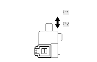
*1 On *2 Off Remove the parking brake switch assembly Click here.
-
Measure the resistance according to the value(s) in the table below.
Standard Resistance Tester Connection Condition Specified Condition 1 - Switch body On (Shaft is not pressed) Below 1 Ω 1 - Switch body Off (Shaft is pressed) 10 kΩ or higher
OK
REPLACE FOLD SEAT CONTROL ECU Click here
NG
REPLACE PARKING BRAKE SWITCH ASSEMBLY Click here
-