FRONT POWER SEAT CONTROL SYSTEM(w/ Memory) Power Seat Position is not Memorized
DESCRIPTION
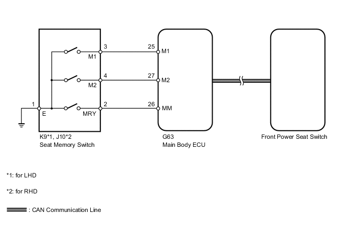
When the seat memory SET switch and a memory switch (M1 or M2) are pressed simultaneously, the main body ECU commands the position control ECU through CAN communication to record the value of each position sensor.
WIRING DIAGRAM
CAUTION / NOTICE / HINT
Note
First perform the communication function inspections in How to Proceed with Troubleshooting to confirm that there are no CAN communication malfunctions before troubleshooting this symptom.
PROCEDURE
-
CHECK FRONT POWER SEAT CONTROL FUNCTION
-
Check that each function of the power seat operates normally by using the front power seat switches.
OK Each function of power seat operates normally by using seat switches.
NG 
GO TO PROBLEM SYMPTOMS TABLE Click here
OK 
-
-
READ VALUE USING INTELLIGENT TESTER (SEAT POSITION MEMORY)
-
Use the seat memory switch to record the seat position Click here.
Note
-
The seat position will not be recorded if the SET switch and both memory switches are pressed simultaneously.
-
If a memorizing operation has failed, release all switches. The seat memory function does not operate unless the switches are released.
-
-
Using the intelligent tester, read the Data List Click here.
Driver Seat Tester Display Measurement Item/Range Normal Condition Diagnostic Note Seat Memory No1 Seat position memorized with M1 switch / Mem or Not Mem Mem: Memorized
Not Mem: Not memorized
- Seat Memory No2 Seat position memorized with M2 switch / Mem or Not Mem Mem: Memorized
Not Mem: Not memorized
- OK "Mem" is displayed on the tester.
OK
END
NG
-
-
READ VALUE USING INTELLIGENT TESTER (SEAT MEMORY SWITCH)
-
Using the intelligent tester, read the Data List Click here.
Main Body Tester Display Measurement Item/Range Normal Condition Diagnostic Note M1 Switch Seat memory switch M1 signal / ON or OFF ON: Seat memory switch M1 on
OFF: Seat memory switch M1 off
- M2 Switch Seat memory switch M2 signal / ON or OFF ON: Seat memory switch M2 on
OFF: Seat memory switch M2 off
- SET Switch Seat memory switch SET signal / ON or OFF ON: Seat memory switch SET on
OFF: Seat memory switch SET off
- OK On intelligent tester screen, each item changes between ON and OFF according to above chart.
NG 
INSPECT SEAT MEMORY SWITCH Click here
OK
-
-
CHECK FRONT POWER SEAT SWITCH (OPERATION)
-
Replace the front power seat switch with a new one or normally operating one.
-
Use the seat memory switch to record the seat position Click here.
-
Refer to the Data List for the driver seat and check that the memory operation is completed normally.
OK Seat position is recorded normally.
OK
END (FRONT POWER SEAT SWITCH WAS DEFECTIVE)
NG
REPLACE MAIN BODY ECU (MULTIPLEX NETWORK BODY ECU) Click here
-
-
INSPECT SEAT MEMORY SWITCH
-
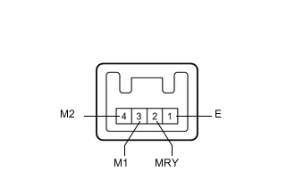
Remove the seat memory switch Click here.
-
Measure the resistance according to the value(s) in the table below.
Standard Resistance Tester Connection Switch Condition Specified Condition 3 (M1) - 1 (E) Seat memory switch M1 pressed Below 1 Ω 4 (M2) - 1 (E) Seat memory switch M2 pressed Below 1 Ω 2 (MRY) - 1 (E) Seat memory switch SET pressed Below 1 Ω
NG
REPLACE SEAT MEMORY SWITCH Click here
OK
-
-
CHECK HARNESS AND CONNECTOR (SEAT MEMORY SWITCH - MAIN BODY ECU AND BODY GROUND)
-
Disconnect the K9*1 or J10*2 switch connector.
-
*1: for LHD
-
*2: for RHD
-
-
Disconnect the G63 ECU connector.
-
Measure the resistance according to the value(s) in the table below.
Standard Resistance for LHD Tester Connection Condition Specified Condition G63-25 (M1) - K9-3 (M1) Always Below 1 Ω G63-27 (M2) - K9-4 (M2) Always Below 1 Ω G63-26 (MM) - K9-2 (MRY) Always Below 1 Ω K9-1 (E) - Body ground Always Below 1 Ω G63-25 (M1) - Body ground Always 10 kΩ or higher G63-27 (M2) - Body ground Always 10 kΩ or higher G63-26 (MM) - Body ground Always 10 kΩ or higher for RHD Tester Connection Condition Specified Condition G63-25 (M1) - J10-3 (M1) Always Below 1 Ω G63-27 (M2) - J10-4 (M2) Always Below 1 Ω G63-26 (MM) - J10-2 (MRY) Always Below 1 Ω J10-1 (E) - Body ground Always Below 1 Ω G63-25 (M1) - Body ground Always 10 kΩ or higher G63-27 (M2) - Body ground Always 10 kΩ or higher G63-26 (MM) - Body ground Always 10 kΩ or higher
OK
REPLACE MAIN BODY ECU (MULTIPLEX NETWORK BODY ECU) Click here
NG
REPAIR OR REPLACE HARNESS OR CONNECTOR
-