SPIRAL CABLE INSTALLATION
CAUTION / NOTICE / HINT
Tech Tips
-
Use the same procedure for RHD and LHD vehicles.
-
The procedure listed below is for LHD vehicles.
PROCEDURE
-
INSPECT SPIRAL CABLE SUB-ASSEMBLY
-
Check that the spiral cable sub-assembly is center position.
OK The connector is at the top. The matchmarks are aligned. The colored roller or the top of the flat cable U-turn can be checked from the check window. 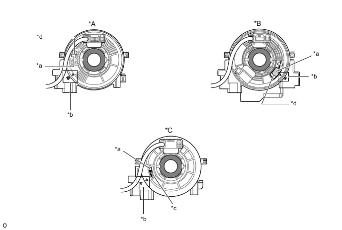
*A Flat Cable (Visible Type), w/o Steering Haeter *B Flat Cable (Visible Type), w/ Steering Heater *C Colored Roller (Visible Type) - - *a Check Window *b Matchmark *c Colored Roller *d Top of Flat Cable U-turn -
If the spiral cable sub-assembly is not centered, center it.
Note
Failure to observe the following precautions may result in damage to the spiral cable sub-assembly .
-
When rotating the spiral cable sub-assembly , make sure to push on the interlock to release the interlock.
-
Do not turn the spiral cable sub-assembly using the airbag wire harness.
-
Do not forcibly rotate the part.
-

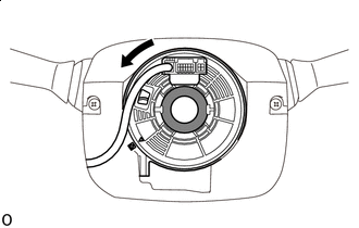
Interlock 
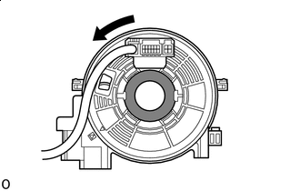
Counterclockwise While pushing on the interlock indicated in the illustration. Make sure to rotate the spiral cable sub-assembly counterclockwise slowly by hand until it stops.
Note
Make sure to rotate the spiral cable sub-assembly counterclockwise. If rotated clockwise, it may be damaged or centering may no longer be possible.
Tech Tips
The interlock operates at the top and bottom of the connector.
-
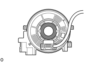
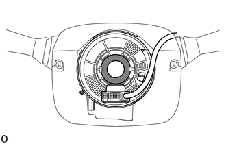
If the spiral cable sub-assembly stops rotating and the connector has moved past the bottom, return the connector to the bottom as shown in the illustration.
-
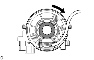
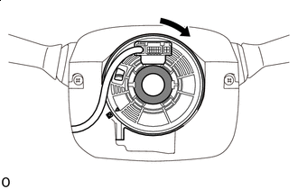
Interlock Counterclockwise While pushing on the interlock, rotate the spiral cable sub-assembly clockwise approximately 2.5 times to move the connector from the bottom to the top.
Note
If the connector is rotated clockwise from the bottom 5 times or more, the spiral cable sub-assembly may be damaged.
Tech Tips
The interlock operates at the top and bottom of the connector.
-
-
Check that the spiral cable sub-assembly is center position.
OK The connector is at the top. The matchmarks are aligned. The colored roller or the top of the flat cable U-turn can be checked from the check window.
*A Flat Cable (Visible Type), w/o Steering Haeter *B Flat Cable (Visible Type), w/ Steering Heater *C Colored Roller (Visible Type) - - *a Check Window *b Matchmark *c Colored Roller *d Top of Flat Cable U-turn Note
If the spiral cable sub-assembly cannot be centered, it is possible that the spiral cable sub-assembly is broken. Replace the spiral cable sub-assembly with a new one.
-
-
INSTALL SPIRAL CABLE SUB-ASSEMBLY
-
Check that the ignition switch is off.
-
Check that the cable is disconnected from the negative (-) battery terminal.
CAUTION:
Wait at least 90 seconds after disconnecting the cable from the negative (-) battery terminal to disable the SRS system.
-
Attach the 3 claws to install the spiral cable sub-assembly.
CAUTION:
When replacing the spiral cable sub-assembly with a new one, remove the lock pin before installing the steering wheel assembly.
-
Connect the connectors to the spiral cable sub-assembly.
Note
When handling the airbag connector, take care not to damage the airbag wire harness.
-
-
INSTALL UPPER STEERING COLUMN COVER
-
for Manual Tilt and Manual Telescopic Steering Column:
-
Install the upper steering column cover Click here.
-
-
for Power Tilt and Power Telescopic Steering Column:
-
Install the upper steering column cover Click here.
-
-
-
INSTALL LOWER STEERING COLUMN COVER
-
for Manual Tilt and Manual Telescopic Steering Column:
-
Install the lower steering column cover Click here.
-
-
for Power Tilt and Power Telescopic Steering Column:
-
Install the lower steering column cover Click here.
-
-
-
TURN FRONT WHEELS TO FACE STRAIGHT AHEAD
-
ADJUST SPIRAL CABLE SUB-ASSEMBLY
Note
Do not adjust the spiral with sensor cable sub-assembly with the battery connected and the ignition switch ON.
-
Check that the ignition switch is off.
-
Check that the cable is disconnected from the negative (-) battery terminal.
CAUTION:
Wait at least 90 seconds after disconnecting the cable from the negative (-) battery terminal to disable the SRS system.
-
Check that the spiral with sensor cable sub-assembly is center position.
OK The connector is at the top. The colored roller or the top of the flat cable U-turn can be checked from the check window. 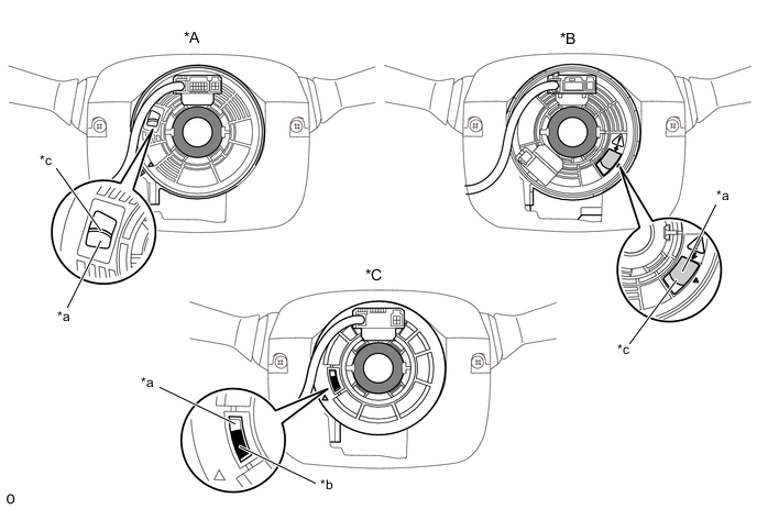
*A Flat Cable (Visible Type), w/o Steering Haeter *B Flat Cable (Visible Type), w/ Steering Heater *C Colored Roller (Visible Type) - - *a Check Window *b Colored Roller *c Top of Flat Cable U-turn - - -
If the spiral with sensor cable sub-assembly is not centered, center it.
Note
Failure to observe the following precautions may result in damage to the spiral with sensor cable sub-assembly.
-
When rotating the spiral with sensor cable sub-assembly, make sure to push on the interlock to release the interlock.
-
Do not turn the spiral with sensor cable sub-assembly using the airbag wire harness.
-
Do not forcibly rotate the part.
-
Interlock Counterclockwise While pushing on the interlock indicated in the illustration. Make sure to rotate the spiral with sensor cable sub-assembly counterclockwise slowly by hand until it stops.
Note
If the connector is rotated clockwise from the bottom 5 times or more, the spiral with sensor cable sub-assembly may be damaged.
Tech Tips
The interlock operates at the top and bottom of the connector.
-
If the spiral with sensor cable sub-assembly stops rotating and the connector has moved past the bottom, return the connector to the bottom as shown in the illustration.
-
Interlock Clockwise While pushing on the interlock, rotate the spiral with sensor cable sub-assembly clockwise approximately 2.5 times to move the connector from the bottom to the top.
Note
If the connector is rotated clockwise from the bottom 5 times or more, the spiral with sensor cable sub-assembly may be damaged.
Tech Tips
The interlock operates at the top and bottom of the connector.
-
Check that the spiral with sensor cable sub-assembly is center position.
OK The connector is at the top. The colored roller or the top of the flat cable U-turn can be checked from the check window. 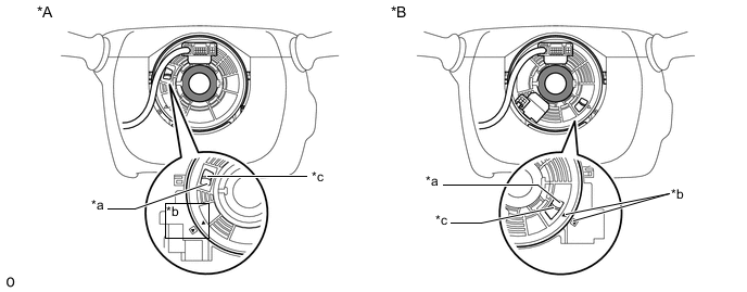
*A w/o Steering Heater *B w/ Steering Heater *a Check Window *b Matchmark *c Top of Flat Cable U-turn - - Note
If the spiral with sensor cable sub-assembly cannot be centered, it is possible that the spiral cable sub-assembly is broken. Replace the spiral cable sub-assembly with a new one.
-
-
-
INSTALL STEERING WHEEL ASSEMBLY
-
Install the steering wheel assembly Click here.
-