CAN COMMUNICATION SYSTEM(for LHD with Entry and Start System) Short in CAN Bus Lines
DESCRIPTION
There may be a short circuit between the CAN bus lines when the resistance between terminals 6 (CANH) and 14 (CANL) of the DLC3 is below 53 Ω.
| Symptom | Trouble Area |
|---|---|
| The resistance between terminals 6 (CANH) and 14 (CANL) of the DLC3 is below 53 Ω. |
|
-
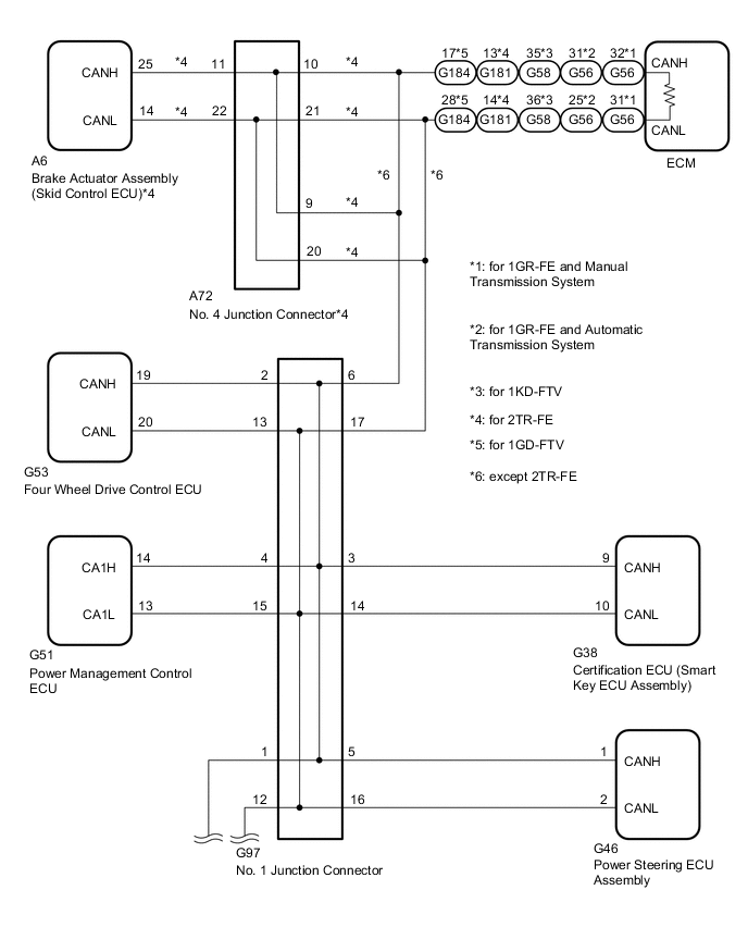
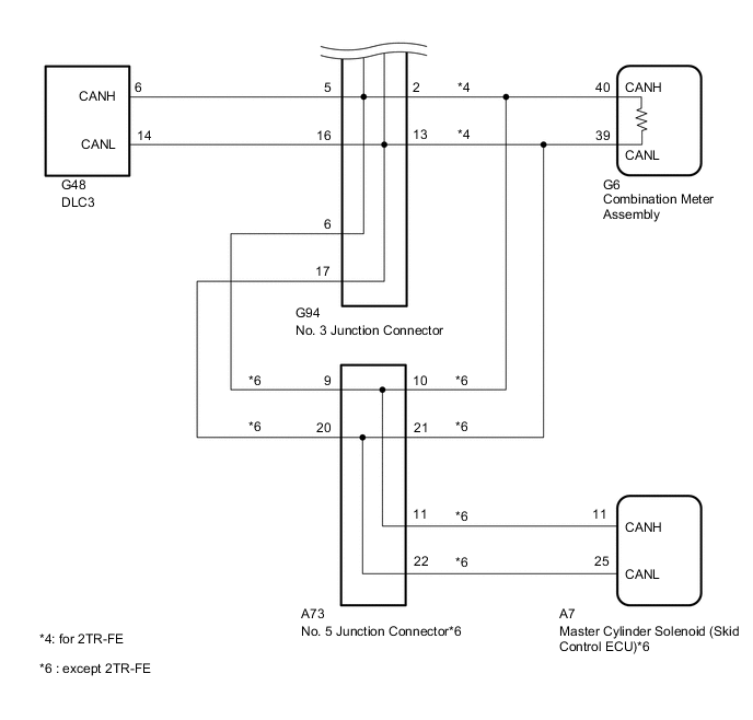
*1: for 2TR-FE
-
*2: for 1GR-FE, 1KD-FTV, 1GD-FTV
-
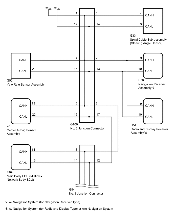
*3: w/ Navigation System (for Navigation Receiver Type)
-
*4: w/ Navigation System (for Radio and Display Type) or w/o Navigation System
WIRING DIAGRAM
CAUTION / NOTICE / HINT
Tech Tips
Operating the engine switch, any switches or any doors triggers related ECU and sensor communication with the CAN, which causes resistance variation.
PROCEDURE
-
DISCONNECT CABLE FROM NEGATIVE BATTERY TERMINAL
-
Disconnect the cable from the negative (-) battery terminal before measuring the resistances of the CAN main wire and the CAN branch wire.
CAUTION:
Wait at least 90 seconds after disconnecting the cable from the negative (-) battery terminal to disable the airbag system.
Note
-
After turning the engine switch off, waiting time may be required before disconnecting the cable from the battery terminal. Therefore, make sure to read the disconnecting the cable from the battery terminal notice before proceeding with work Click here.
-
When disconnecting the cable, some systems need to be initialized after the cable is reconnected Click here.
-
NEXT 
-
-
CHECK FOR SHORT IN CAN BUS WIRES (DLC3 CAN BRANCH WIRE)
-
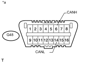
Text in Illustration *a Front view of DLC3 Disconnect the G94 No. 3 junction connector.
-
Measure the resistance according to the value(s) in the table below.
Standard Resistance Tester Connection Switch Condition Specified Condition G48-6 (CANH) - G48-14 (CANL) Engine switch off 1 MΩ or higher
NG 
REPAIR OR REPLACE CAN BRANCH WIRE CONNECTED TO DLC3 (CANH, CANL)
OK
-
-
CONNECT CONNECTOR
-
Reconnect the G94 No. 3 junction connector.
NEXT
-
-
CHECK FOR SHORT IN CAN BUS WIRES (NO. 1 JUNCTION CONNECTOR SIDE)
-
Text in Illustration *a Front view of DLC3 Disconnect the G97 No. 1 junction connector.
-
Measure the resistance according to the value(s) in the table below.
Standard Resistance Tester Connection Switch Condition Specified Condition G48-6 (CANH) - G48-14 (CANL) Engine switch off 108 to 132 Ω
NG 
CONNECT CONNECTOR Click here
OK
-
-
CHECK FOR SHORT IN CAN BUS WIRES (NO. 1 JUNCTION CONNECTOR - FOUR WHEEL DRIVE CONTROL ECU)
-

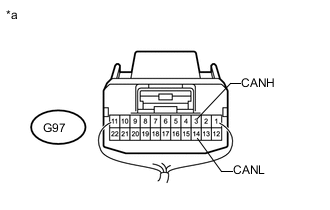
Text in Illustration *a Rear view of wire harness connector
(to No. 1 Junction Connector)
Measure the resistance according to the value(s) in the table below.
Standard Resistance Tester Connection Switch Condition Specified Condition G97-2 (CANH) - G97-13 (CANL) Engine switch off 200 Ω or higher
NG
CONNECT CONNECTOR Click here
OK
-
-
CHECK FOR SHORT IN CAN BUS WIRES (NO. 1 JUNCTION CONNECTOR - CERTIFICATION ECU)
-
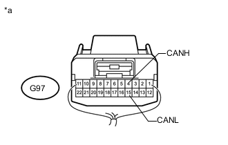
Text in Illustration *a Rear view of wire harness connector
(to No. 1 Junction Connector)
Measure the resistance according to the value(s) in the table below.
Standard Resistance Tester Connection Switch Condition Specified Condition G97-3 (CANH) - G97-14 (CANL) Engine switch off 200 Ω or higher
NG
CONNECT CONNECTOR Click here
OK
-
-
CHECK FOR SHORT IN CAN BUS WIRES (NO. 1 JUNCTION CONNECTOR - POWER MANAGEMENT CONTROL ECU)
-
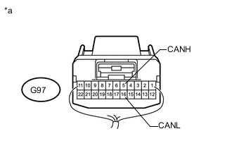
Text in Illustration *a Rear view of wire harness connector
(to No. 1 Junction Connector)
Measure the resistance according to the value(s) in the table below.
Standard Resistance Tester Connection Switch Condition Specified Condition G97-4 (CANH) - G97-15 (CANL) Engine switch off 200 Ω or higher
NG
CONNECT CONNECTOR Click here
OK
-
-
CHECK FOR SHORT IN CAN BUS WIRES (NO. 1 JUNCTION CONNECTOR - POWER STEERING ECU ASSEMBLY)
-
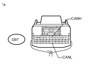
Text in Illustration *a Rear view of wire harness connector
(to No. 1 Junction Connector)
Measure the resistance according to the value(s) in the table below.
Standard Resistance Tester Connection Switch Condition Specified Condition G97-5 (CANH) - G97-16 (CANL) Engine switch off 200 Ω or higher
NG
CONNECT CONNECTOR Click here
OK
-
-
CHECK FOR SHORT IN CAN BUS WIRES (NO. 1 JUNCTION CONNECTOR - ECM OR NO. 4 JUNCTION CONNECTOR)
-
Text in Illustration *a Rear view of wire harness connector
(to No. 1 Junction Connector)
Measure the resistance according to the value(s) in the table below.
Standard Resistance Tester Connection Switch Condition Specified Condition G97-6 (CANH) - G97-17 (CANL) Engine switch off 108 to 132 Ω Result Result Proceed to OK A NG (for 1GR-FE) B NG (for 1KD-FTV) C NG (for 1GD-FTV) D NG (for 2TR-FE) E
A
REPLACE NO. 1 JUNCTION CONNECTOR
B
CONNECT CONNECTOR Click here
C
CONNECT CONNECTOR Click here
D
CONNECT CONNECTOR Click here
E
CONNECT CONNECTOR Click here
-
-
CONNECT CONNECTOR
-
Reconnect the G97 No. 1 junction connector.
NEXT
-
-
CHECK FOR SHORT IN CAN BUS WIRES (FOUR WHEEL DRIVE CONTROL ECU)
-
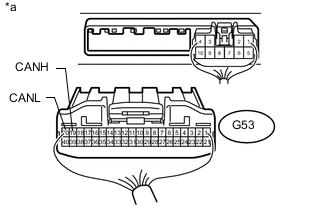
Text in Illustration *a Rear view of wire harness connector
(to Four Wheel Drive Control ECU)
Disconnect the G53 four wheel drive control ECU connector.
-
Measure the resistance according to the value(s) in the table below.
Standard Resistance Tester Connection Switch Condition Specified Condition G53-19 (CANH) - G53-20 (CANL) Engine switch off 54 to 69 Ω
OK
REPLACE FOUR WHEEL DRIVE CONTROL ECU Click here
NG
REPAIR OR REPLACE CAN BRANCH WIRE CONNECTED TO FOUR WHEEL DRIVE CONTROL ECU (CANH, CANL)
-
-
CONNECT CONNECTOR
-
Reconnect the G97 No. 1 junction connector.
NEXT
-
-
CHECK FOR SHORT IN CAN BUS WIRES (CERTIFICATION ECU)
-
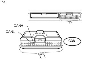
Text in Illustration *a Rear view of wire harness connector
(to Certification ECU [Smart Key ECU Assembly])
Disconnect the G38 certification ECU (smart key ECU assembly) connector.
-
Measure the resistance according to the value(s) in the table below.
Standard Resistance Tester Connection Switch Condition Specified Condition G38-9 (CANH) - G38-10 (CANL) Engine switch off 54 to 69 Ω
OK
REPLACE CERTIFICATION ECU (SMART KEY ECU ASSEMBLY)
NG
REPAIR OR REPLACE CAN BRANCH WIRE CONNECTED TO CERTIFICATION ECU (CANH, CANL)
-
-
CONNECT CONNECTOR
-
Reconnect the G97 No. 1 junction connector.
NEXT
-
-
CHECK FOR SHORT IN CAN BUS WIRES (POWER MANAGEMENT CONTROL ECU)
-
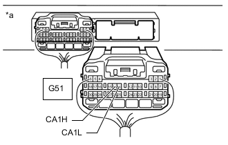
Text in Illustration *a Rear view of wire harness connector
(to Power Management Control ECU)
Disconnect the G51 power management control ECU connector.
-
Measure the resistance according to the value(s) in the table below.
Standard Resistance Tester Connection Switch Condition Specified Condition G51-14 (CA1H) - G51-13 (CA1L) Engine switch off 54 to 69 Ω
OK
REPLACE POWER MANAGEMENT CONTROL ECU Click here
NG
REPAIR OR REPLACE CAN BRANCH WIRE CONNECTED TO POWER MANAGEMENT CONTROL ECU (CA1H, CA1L)
-
-
CONNECT CONNECTOR
-
Reconnect the G97 No. 1 junction connector.
NEXT
-
-
CHECK FOR SHORT IN CAN BUS WIRES (POWER STEERING ECU ASSEMBLY)
-
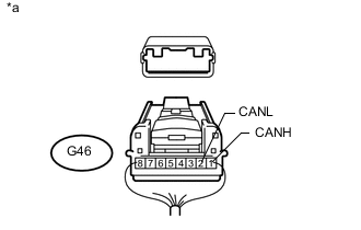
Text in Illustration *a Rear view of wire harness connector
(to Power Steering ECU Assembly)
Disconnect the G46 power steering ECU assembly connector.
-
Measure the resistance according to the value(s) in the table below.
Standard Resistance Tester Connection Switch Condition Specified Condition G46-1 (CANH) - G46-2 (CANL) Engine switch off 54 to 69 Ω
OK
REPLACE POWER STEERING ECU ASSEMBLY Click here
NG
REPAIR OR REPLACE CAN BRANCH WIRE CONNECTED TO POWER STEERING ECU ASSEMBLY (CANH, CANL)
-
-
CONNECT CONNECTOR
-
Reconnect the G97 No. 1 junction connector.
NEXT
-
-
CHECK FOR SHORT IN CAN BUS WIRES (ECM)
-
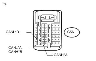
Text in Illustration *A for Manual Transmission System *B for Automatic Transmission System *a Front view of wire harness connector
(to ECM)
Disconnect the G56 ECM connector.
-
Measure the resistance according to the value(s) in the table below.
Standard Resistance for Manual Transmission System Tester Connection Switch Condition Specified Condition G56-32 (CANH) - G56-31 (CANL) Engine switch off 108 to 132 Ω for Automatic Transmission System Tester Connection Switch Condition Specified Condition G56-31 (CANH) - G56-25 (CANL) Engine switch off 108 to 132 Ω
OK
REPLACE ECM Click here
NG
REPAIR OR REPLACE CAN MAIN WIRE CONNECTED TO ECM (CANH, CANL)
-
-
CONNECT CONNECTOR
-
Reconnect the G97 No. 1 junction connector.
NEXT
-
-
CHECK FOR SHORT IN CAN BUS WIRES (ECM)
-
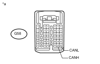
Text in Illustration *a Front view of wire harness connector
(to ECM)
Disconnect the G58 ECM connector.
-
Measure the resistance according to the value(s) in the table below.
Standard Resistance Tester Connection Switch Condition Specified Condition G58-35 (CANH) - G58-36 (CANL) Engine switch off 108 to 132 Ω
OK
REPLACE ECM Click here
NG
REPAIR OR REPLACE CAN MAIN WIRE CONNECTED TO ECM (CANH, CANL)
-
-
CONNECT CONNECTOR
-
Reconnect the G97 No. 1 junction connector.
NEXT
-
-
CHECK FOR SHORT IN CAN BUS WIRES (ECM)
-
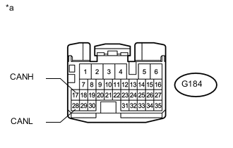
Text in Illustration *a Front view of wire harness connector
(to ECM)
Disconnect the G184 ECM connector.
-
Measure the resistance according to the value(s) in the table below.
Standard Resistance Tester Connection Switch Condition Specified Condition G184-17 (CANH) - G187-28 (CANL) Engine switch off 108 to 132 Ω
OK
REPLACE ECM Click here
NG
REPAIR OR REPLACE CAN MAIN WIRE CONNECTED TO ECM (CANH, CANL)
-
-
CONNECT CONNECTOR
-
Reconnect the G97 No. 1 junction connector.
NEXT
-
-
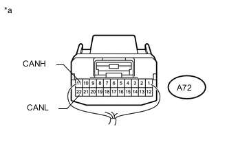
CHECK FOR SHORT IN CAN BUS WIRES (NO. 4 JUNCTION CONNECTOR - NO. 1 JUNCTION CONNECTOR)
-

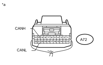
Text in Illustration *a Rear view of wire harness connector
(to No. 4 Junction Connector)
Disconnect the A72 No. 4 junction connector.
-
Measure the resistance according to the value(s) in the table below.
Standard Resistance Tester Connection Switch Condition Specified Condition A72-9 (CANH) - A72-20 (CANL) Engine switch off 108 to 132 Ω
NG
REPAIR OR REPLACE CAN MAIN WIRE OR CONNECTOR (NO. 4 JUNCTION CONNECTOR - NO. 1 JUNCTION CONNECTOR)
OK
-
-
CHECK FOR SHORT IN CAN BUS WIRES (NO. 4 JUNCTION CONNECTOR - SKID CONTROL ECU)
-
Text in Illustration *a Rear view of wire harness connector
(to No. 4 Junction Connector)
Measure the resistance according to the value(s) in the table below.
Standard Resistance Tester Connection Switch Condition Specified Condition A72-11 (CANH) - A72-22 (CANL) Engine switch off 200 Ω or higher
NG
CONNECT CONNECTOR Click here
OK
-
-
CHECK FOR SHORT IN CAN BUS WIRES (NO. 4 JUNCTION CONNECTOR - ECM)
-
Text in Illustration *a Rear view of wire harness connector
(to No. 4 Junction Connector)
Measure the resistance according to the value(s) in the table below.
Standard Resistance Tester Connection Switch Condition Specified Condition A72-10 (CANH) - A72-21 (CANL) Engine switch off 108 to 132 Ω
OK
REPLACE NO. 4 JUNCTION CONNECTOR
NG
CONNECT CONNECTOR Click here
-
-
CONNECT CONNECTOR
-
Reconnect the A72 No. 4 junction connector.
NEXT
-
-
CHECK FOR SHORT IN CAN BUS WIRES (SKID CONTROL ECU)
-
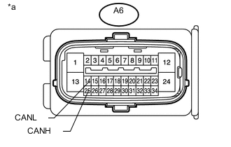
Text in Illustration *a Front view of wire harness connector
(to Brake Actuator Assembly [Skid Control ECU])
Disconnect the A6 brake actuator assembly (skid control ECU) connector.
-
Measure the resistance according to the value(s) in the table below.
Standard Resistance Tester Connection Switch Condition Specified Condition A6-25 (CANH) - A6-14 (CANL) Engine switch off 54 to 69 Ω
OK
REPLACE BRAKE ACTUATOR ASSEMBLY (SKID CONTROL ECU) Click here
NG
REPAIR OR REPLACE CAN BRANCH WIRE CONNECTED TO SKID CONTROL ECU (CANH, CANL)
-
-
CONNECT CONNECTOR
-
Reconnect the A72 No. 4 junction connector.
NEXT
-
-
CHECK FOR SHORT IN CAN BUS WIRES (ECM)
-
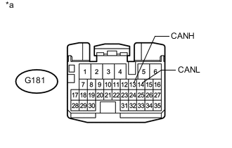
Text in Illustration *a Front view of wire harness connector
(to ECM)
Disconnect the G181 ECM connector.
-
Measure the resistance according to the value(s) in the table below.
Standard Resistance Tester Connection Switch Condition Specified Condition G181-13 (CANH) - G181-14 (CANL) Engine switch off 108 to 132 Ω
OK
REPLACE ECM Click here
NG
REPAIR OR REPLACE CAN MAIN WIRE CONNECTED TO ECM (CANH, CANL)
-
-
CONNECT CONNECTOR
-
Reconnect the G97 No. 1 junction connector.
NEXT
-
-
CHECK FOR SHORT IN CAN BUS WIRES (NO. 2 JUNCTION CONNECTOR - NO. 1 JUNCTION CONNECTOR)
-
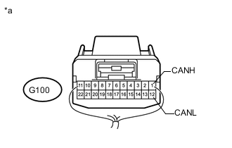
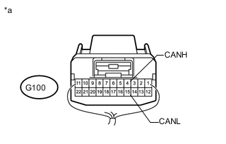
Text in Illustration *a Rear view of wire harness connector
(to No. 2 Junction Connector)
Disconnect the G100 No. 2 junction connector.
-
Measure the resistance according to the value(s) in the table below.
Standard Resistance Tester Connection Switch Condition Specified Condition G100-1 (CANH) - G100-12 (CANL) Engine switch off 108 to 132 Ω
NG
REPAIR OR REPLACE CAN MAIN WIRE OR CONNECTOR (NO. 2 JUNCTION CONNECTOR - NO. 1 JUNCTION CONNECTOR)
OK
-
-
CHECK FOR SHORT IN CAN BUS WIRES (NO. 2 JUNCTION CONNECTOR SIDE)
-
Text in Illustration *a Front view of DLC3 Measure the resistance according to the value(s) in the table below.
Standard Resistance Tester Connection Switch Condition Specified Condition G48-6 (CANH) - G48-14 (CANL) Engine switch off 108 to 132 Ω
NG
CONNECT CONNECTOR Click here
OK
-
-
CHECK FOR SHORT IN CAN BUS WIRES (NO. 2 JUNCTION CONNECTOR - NAVIGATION RECEIVER ASSEMBLY)
Note
For vehicles without a navigation system (for navigation receiver type), go to "Check for Short in CAN Bus Wires (No. 2 Junction Connector - Radio and Display Receiver Assembly)".
-

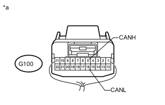
Text in Illustration *a Rear view of wire harness connector
(to No. 2 Junction Connector)
Measure the resistance according to the value(s) in the table below.
Standard Resistance Tester Connection Switch Condition Specified Condition G100-2 (CANH) - G100- 13 (CANL) Engine switch off 200 Ω or higher
NG
CONNECT CONNECTOR Click here
OK
-
-
CHECK FOR SHORT IN CAN BUS WIRES (NO. 2 JUNCTION CONNECTOR - RADIO AND DISPLAY RECEIVER ASSEMBLY)
Note
For vehicles with a navigation system (for navigation receiver type), go to "Check for Short in CAN Bus Wires (No. 2 Junction Connector - Steering Angle Sensor)".
-
Text in Illustration *a Rear view of wire harness connector
(to No. 2 Junction Connector)
Measure the resistance according to the value(s) in the table below.
Standard Resistance Tester Connection Switch Condition Specified Condition G100-2 (CANH) - G100- 13 (CANL) Engine switch off 200 Ω or higher
NG
CONNECT CONNECTOR Click here
OK
-
-
CHECK FOR SHORT IN CAN BUS WIRES (NO. 2 JUNCTION CONNECTOR - STEERING ANGLE SENSOR)
-

Text in Illustration *a Rear view of wire harness connector
(to No. 2 Junction Connector)
Measure the resistance according to the value(s) in the table below.
Standard Resistance Tester Connection Switch Condition Specified Condition G100-3 (CANH) - G100- 14 (CANL) Engine switch off 200 Ω or higher
NG
CONNECT CONNECTOR Click here
OK
-
-
CHECK FOR SHORT IN CAN BUS WIRES (NO. 2 JUNCTION CONNECTOR - YAW RATE SENSOR ASSEMBLY)
-
Text in Illustration *a Rear view of wire harness connector
(to No. 2 Junction Connector)
Measure the resistance according to the value(s) in the table below.
Standard Resistance Tester Connection Switch Condition Specified Condition G100-4 (CANH) - G100- 15 (CANL) Engine switch off 200 Ω or higher
NG
CONNECT CONNECTOR Click here
OK
-
-
CHECK FOR SHORT IN CAN BUS WIRES (NO. 2 JUNCTION CONNECTOR - CENTER AIRBAG SENSOR ASSEMBLY)
-
Text in Illustration *a Rear view of wire harness connector
(to No. 2 Junction Connector)
Measure the resistance according to the value(s) in the table below.
Standard Resistance Tester Connection Switch Condition Specified Condition G100-5 (CANH) - G100- 16 (CANL) Engine switch off 200 Ω or higher
OK
REPLACE NO. 2 JUNCTION CONNECTOR
NG
CONNECT CONNECTOR Click here
-
-
CONNECT CONNECTOR
-
Reconnect the G100 No. 2 junction connector.
NEXT
-
-
CHECK FOR SHORT IN CAN BUS WIRES (NAVIGATION RECEIVER ASSEMBLY)
-
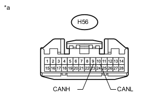
Text in Illustration *a Front view of wire harness connector
(to Navigation Receiver Assembly)
Disconnect the H56 navigation receiver assembly connector.
-
Measure the resistance according to the value(s) in the table below.
Standard Resistance Tester Connection Switch Condition Specified Condition H56-9 (CANH) - H56-10 (CANL) Engine switch off 54 to 69 Ω
OK
REPLACE NAVIGATION RECEIVER ASSEMBLY Click here
NG
REPAIR OR REPLACE CAN BRANCH WIRE CONNECTED TO NAVIGATION RECEIVER ASSEMBLY (CANH, CANL)
-
-
CONNECT CONNECTOR
-
Reconnect the G100 No. 2 junction connector.
NEXT
-
-
CHECK FOR SHORT IN CAN BUS WIRES (RADIO AND DISPLAY RECEIVER ASSEMBLY)
-
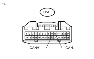
Text in Illustration *a Front view of wire harness connector
(to Radio and Display Receiver Assembly)
Disconnect the H51 radio and display receiver assembly connector.
-
Measure the resistance according to the value(s) in the table below.
Standard Resistance Tester Connection Switch Condition Specified Condition H51-9 (CANH) - H51-10 (CANL) Engine switch off 54 to 69 Ω
OK
REPLACE RADIO AND DISPLAY RECEIVER ASSEMBLY Click here
NG
REPAIR OR REPLACE CAN BRANCH WIRE CONNECTED TO RADIO AND DISPLAY RECEIVER ASSEMBLY (CANH, CANL)
-
-
CONNECT CONNECTOR
-
Reconnect the G100 No. 2 junction connector.
NEXT
-
-
CHECK FOR SHORT IN CAN BUS WIRES (STEERING ANGLE SENSOR)
-
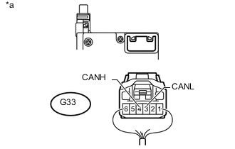
Text in Illustration *a Rear view of wire harness connector
(to Spiral Cable Sub-assembly [Steering Angle Sensor])
Disconnect the G33 spiral cable sub-assembly (steering angle sensor) connector.
-
Measure the resistance according to the value(s) in the table below.
Standard Resistance Tester Connection Switch Condition Specified Condition G33-4 (CANH) - G33-3 (CANL) Engine switch off 54 to 69 Ω
OK
REPLACE SPIRAL CABLE SUB-ASSEMBLY (STEERING ANGLE SENSOR) Click here
NG
REPAIR OR REPLACE CAN BRANCH WIRE CONNECTED TO STEERING ANGLE SENSOR (CANH, CANL)
-
-
CONNECT CONNECTOR
-
Reconnect the G100 No. 2 junction connector.
NEXT
-
-
CHECK FOR SHORT IN CAN BUS WIRES (YAW RATE SENSOR ASSEMBLY)
-
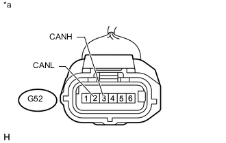
Text in Illustration *a Front view of wire harness connector
(to Yaw Rate Sensor Assembly)
Disconnect the G52 yaw rate sensor assembly connector.
-
Measure the resistance according to the value(s) in the table below.
Standard Resistance Tester Connection Switch Condition Specified Condition G52-3 (CANH) - G52-2 (CANL) Engine switch off 54 to 69 Ω
OK
REPLACE YAW RATE SENSOR ASSEMBLY Click here
NG
REPAIR OR REPLACE CAN BRANCH WIRE CONNECTED TO YAW RATE SENSOR ASSEMBLY (CANH, CANL)
-
-
CONNECT CONNECTOR
-
Reconnect the G100 No. 2 junction connector.
NEXT
-
-
CHECK FOR SHORT IN CAN BUS WIRES (CENTER AIRBAG SENSOR ASSEMBLY)
-
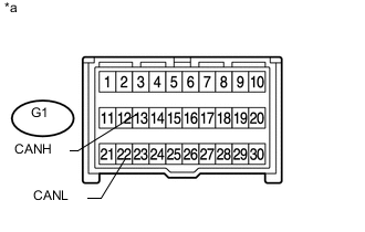
Text in Illustration *a Front view of wire harness connector
(to Center Airbag Sensor Assembly)
Disconnect the G1 center airbag sensor assembly connector.
-
Measure the resistance according to the value(s) in the table below.
Standard Resistance Tester Connection Switch Condition Specified Condition G1-13 (CANH) - G1-22 (CANL) Engine switch off 54 to 69 Ω
OK
REPLACE CENTER AIRBAG SENSOR ASSEMBLY Click here
NG
REPAIR OR REPLACE CAN BRANCH WIRE CONNECTED TO CENTER AIRBAG SENSOR ASSEMBLY (CANH, CANL)
-
-
CONNECT CONNECTOR
-
Reconnect the G100 No. 2 junction connector.
NEXT
-
-
CHECK FOR SHORT IN CAN BUS WIRES (NO. 3 JUNCTION CONNECTOR - NO. 2 JUNCTION CONNECTOR)
-
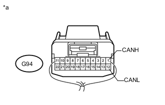
Text in Illustration *a Rear view of wire harness connector
(to No. 3 Junction Connector)
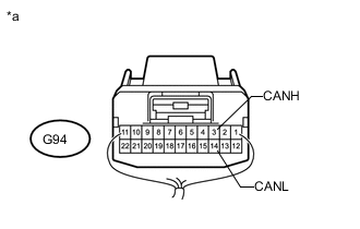
Disconnect the G94 No. 3 junction connector.
-
Measure the resistance according to the value(s) in the table below.
Standard Resistance Tester Connection Switch Condition Specified Condition G94-1 (CANH) - G94-12 (CANL) Engine switch off 108 to 132 Ω
NG
REPAIR OR REPLACE CAN MAIN WIRE OR CONNECTOR (NO. 3 JUNCTION CONNECTOR - NO. 2 JUNCTION CONNECTOR)
OK
-
-
CHECK FOR SHORT IN CAN BUS WIRES (NO. 3 JUNCTION CONNECTOR - MAIN BODY ECU)
-
Text in Illustration *a Rear view of wire harness connector
(to No. 3 Junction Connector)
Measure the resistance according to the value(s) in the table below.
Standard Resistance Tester Connection Switch Condition Specified Condition G94-3 (CANH) - G94-14 (CANL) Engine switch off 200 Ω or higher
NG
CONNECT CONNECTOR Click here
OK
-
-
CHECK FOR SHORT IN CAN BUS WIRES (NO. 3 JUNCTION CONNECTOR - NO. 5 JUNCTION CONNECTOR OR COMBINATION METER ASSEMBLY)
-
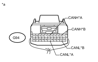
Text in Illustration *A for 1GR-FE, 1KD-FTV, 1GD-FTV *B for 2TR-FE *a Rear view of wire harness connector
(to No. 3 Junction Connector)
Measure the resistance according to the value(s) in the table below.
Standard Resistance for 1GR-FE, 1KD-FTV, 1GD-FTV Tester Connection Switch Condition Specified Condition G94-6 (CANH) - G94-17 (CANL) Engine switch off 108 to 132 Ω for 2TR-FE Tester Connection Switch Condition Specified Condition G94-2 (CANH) - G94-13 (CANL) Engine switch off 108 to 132 Ω Result Result Proceed to OK A NG (for 2TR-FE) B NG (for 1GR-FE, 1KD-FTV, 1GD-FTV) C
A
REPLACE NO. 3 JUNCTION CONNECTOR
B
CONNECT CONNECTOR Click here
C
CONNECT CONNECTOR Click here
-
-
CONNECT CONNECTOR
-
Reconnect the G94 No. 3 junction connector.
NEXT
-
-
CHECK FOR SHORT IN CAN BUS WIRES (MAIN BODY ECU)
-
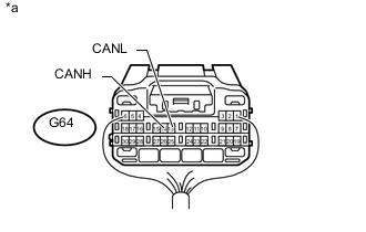
Text in Illustration *a Rear view of wire harness connector
(to Main Body ECU [Multiplex Network Body ECU])
Disconnect the G64 main body ECU (multiplex network body ECU) connector.
-
Measure the resistance according to the value(s) in the table below.
Standard Resistance Tester Connection Switch Condition Specified Condition G64-14 (CANH) - G64-13 (CANL) Engine switch off 54 to 69 Ω
OK
REPLACE MAIN BODY ECU (MULTIPLEX NETWORK BODY ECU) Click here
NG
REPAIR OR REPLACE CAN BRANCH WIRE CONNECTED TO MAIN BODY ECU (CANH, CANL)
-
-
CONNECT CONNECTOR
-
Reconnect the G94 No. 3 junction connector.
NEXT
-
-
CHECK FOR SHORT IN CAN BUS WIRES (COMBINATION METER ASSEMBLY)
-
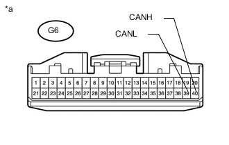
Text in Illustration *a Front view of wire harness connector
(to Combination Meter Assembly)
Disconnect the G6 combination meter assembly connector.
-
Measure the resistance according to the value(s) in the table below.
Standard Resistance Tester Connection Switch Condition Specified Condition G6-40 (CANH) - G6-39 (CANL) Engine switch off 108 to 132 Ω
OK
REPLACE COMBINATION METER ASSEMBLY Click here
NG
REPAIR OR REPLACE CAN MAIN WIRE CONNECTED TO COMBINATION METER ASSEMBLY (CANH, CANL)
-
-
CONNECT CONNECTOR
-
Reconnect the G94 No. 3 junction connector.
NEXT
-
-
CHECK FOR SHORT IN CAN BUS WIRES (NO. 5 JUNCTION CONNECTOR - NO. 3 JUNCTION CONNECTOR)
-
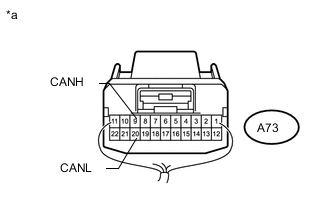
Text in Illustration *a Rear view of wire harness connector
(to No. 5 Junction Connector)
Disconnect the A73 No. 5 junction connector.
-
Measure the resistance according to the value(s) in the table below.
Standard Resistance Tester Connection Switch Condition Specified Condition A73-9 (CANH) - A73-20 (CANL) Engine switch off 108 to 132 Ω
NG
REPAIR OR REPLACE CAN MAIN WIRE OR CONNECTOR (NO. 5 JUNCTION CONNECTOR - NO. 3 JUNCTION CONNECTOR)
OK
-
-
CHECK FOR SHORT IN CAN BUS WIRES (NO. 5 JUNCTION CONNECTOR - SKID CONTROL ECU)
-
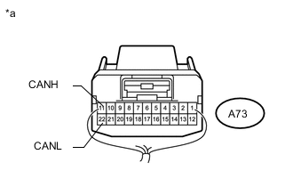
Text in Illustration *a Rear view of wire harness connector
(to No. 5 Junction Connector)
Measure the resistance according to the value(s) in the table below.
Standard Resistance Tester Connection Switch Condition Specified Condition A73-11 (CANH) - A73-22 (CANL) Engine switch off 200 Ω or higher
NG
CONNECT CONNECTOR Click here
OK
-
-
CHECK FOR SHORT IN CAN BUS WIRES (NO. 5 JUNCTION CONNECTOR - COMBINATION METER ASSEMBLY)
-

Text in Illustration *a Rear view of wire harness connector
(to No. 5 Junction Connector)
Measure the resistance according to the value(s) in the table below.
Standard Resistance Tester Connection Switch Condition Specified Condition A73-10 (CANH) - A73-21 (CANL) Engine switch off 108 to 132 Ω
OK
REPLACE NO. 5 JUNCTION CONNECTOR
NG
CONNECT CONNECTOR Click here
-
-
CONNECT CONNECTOR
-
Reconnect the A73 No. 5 junction connector.
NEXT
-
-
CHECK FOR SHORT IN CAN BUS WIRES (SKID CONTROL ECU)
-
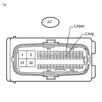
Text in Illustration *a Front view of wire harness connector
(to Master Cylinder Solenoid [Skid Control ECU])
Disconnect the A7 master cylinder solenoid (skid control ECU) connector.
-
Measure the resistance according to the value(s) in the table below.
Standard Resistance Tester Connection Switch Condition Specified Condition A7-11 (CANH) - A7-25 (CANL) Engine switch off 54 to 69 Ω
OK
REPLACE MASTER CYLINDER SOLENOID (SKID CONTROL ECU) Click here
NG
REPAIR OR REPLACE CAN BRANCH WIRE CONNECTED TO SKID CONTROL ECU (CANH, CANL)
-
-
CONNECT CONNECTOR
-
Reconnect the A73 No. 5 junction connector.
NEXT
-
-
CHECK FOR SHORT IN CAN BUS WIRES (COMBINATION METER ASSEMBLY)
-
Text in Illustration *a Front view of wire harness connector
(to Combination Meter Assembly)
Disconnect the G6 combination meter assembly connector.
-
Measure the resistance according to the value(s) in the table below.
Standard Resistance Tester Connection Switch Condition Specified Condition G6-40 (CANH) - G6-39 (CANL) Engine switch off 108 to 132 Ω
OK
REPLACE COMBINATION METER ASSEMBLY Click here
NG
REPAIR OR REPLACE CAN MAIN WIRE CONNECTED TO COMBINATION METER ASSEMBLY (CANH, CANL)
-