CAN COMMUNICATION SYSTEM(for LHD with Entry and Start System) ECM Communication Stop Mode
DESCRIPTION
| Detection Item | Symptom | Trouble Area |
|---|---|---|
| ECM Communication Stop Mode | Either condition is met:
|
|
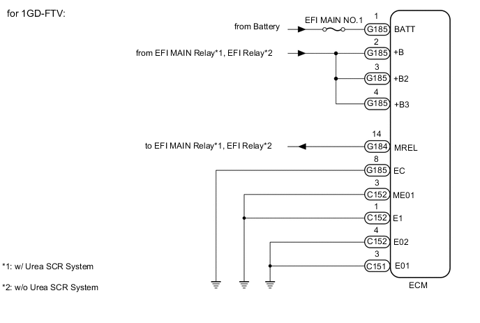
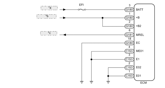
WIRING DIAGRAM
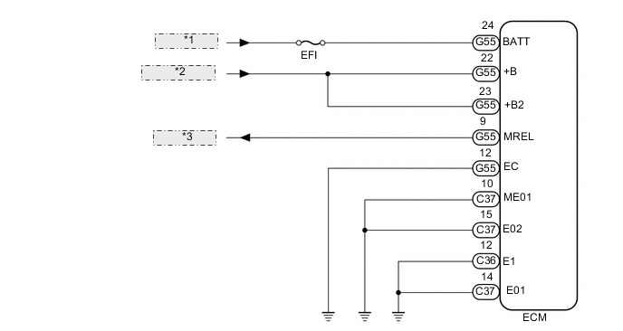
| *1 | from Battery |
| *2 | from EFI Relay |
| *3 | to EFI Relay |
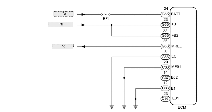
| *a | from Battery |
| *b | from EFI Relay |
| *c | to EFI Relay |
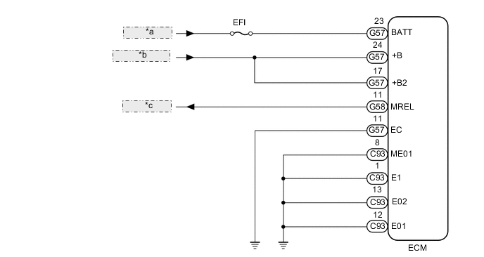
| *a | from Battery |
| *b | from EFI Relay |
| *c | to EFI Relay |
| *a | from Battery |
| *b | from EFI Relay |
| *c | to EFI Relay |
CAUTION / NOTICE / HINT
Note
Inspect the fuses for circuits related to this system before performing the following inspection procedure.
PROCEDURE
-
CHECK HARNESS AND CONNECTOR (ECM - BATTERY AND BODY GROUND)
-
for 1GR-FE and Manual Transmission System:
-
Disconnect the C36, C37 and G55 ECM connectors.
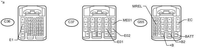
Text in Illustration *a Front view of wire harness connector
(to ECM)
- - -
Measure the resistance according to the value(s) in the table below.
Standard Resistance Tester Connection Condition Specified Condition C36-12 (E1) - Body ground Always Below 1 Ω C37-14 (E01) - Body ground Always Below 1 Ω C37-15 (E02) - Body ground Always Below 1 Ω C37-10 (ME01) - Body ground Always Below 1 Ω G55-12 (EC) - Body ground Always Below 1 Ω -
Measure the voltage according to the value(s) in the table below.
Standard Voltage Tester Connection Condition Specified Condition G55-24 (BATT) - Body ground Always 11 to 14 V G55-23 (+B2) - Body ground Battery positive (+) voltage applied to terminal G55-9 (MREL) 11 to 14 V G55-22 (+B) - Body ground Battery positive (+) voltage applied to terminal G55-9 (MREL) 11 to 14 V
-
-
for 1GR-FE and Automatic Transmission System:
-
Disconnect the C36, C37, G55 and G56 ECM connectors.
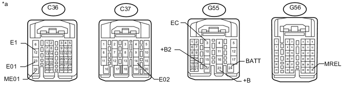
Text in Illustration *a Front view of wire harness connector
(to ECM)
- - -
Measure the resistance according to the value(s) in the table below.
Standard Resistance Tester Connection Condition Specified Condition C36-12 (E1) - Body ground Always Below 1 Ω C36-23 (E01) - Body ground Always Below 1 Ω C37-14 (E02) - Body ground Always Below 1 Ω C36-29 (ME01) - Body ground Always Below 1 Ω G55-3 (EC) - Body ground Always Below 1 Ω -
Measure the voltage according to the value(s) in the table below.
Standard Voltage Tester Connection Condition Specified Condition G55-24 (BATT) - Body ground Always 11 to 14 V G55-22 (+B2) - Body ground Battery positive (+) voltage applied to terminal G56-36 (MREL) 11 to 14 V G55-23 (+B) - Body ground Battery positive (+) voltage applied to terminal G56-36 (MREL) 11 to 14 V
-
-
for 1KD-FTV:
-
Disconnect the C93, G57 and G58 ECM connectors.
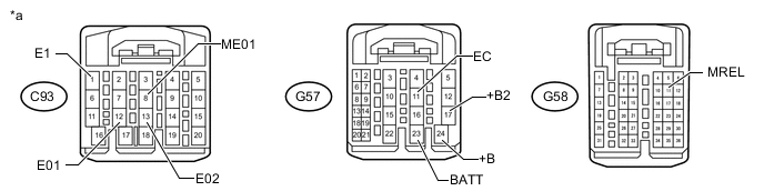
Text in Illustration *a Front view of wire harness connector
(to ECM)
- - -
Measure the resistance according to the value(s) in the table below.
Standard Resistance Tester Connection Condition Specified Condition C93-1 (E1) - Body ground Always Below 1 Ω C93-12 (E01) - Body ground Always Below 1 Ω C93-13 (E02) - Body ground Always Below 1 Ω C93-8 (ME01) - Body ground Always Below 1 Ω G57-11 (EC) - Body ground Always Below 1 Ω -
Measure the voltage according to the value(s) in the table below.
Standard Voltage Tester Connection Condition Specified Condition G57-23 (BATT) - Body ground Always 11 to 14 V G57-17 (+B2) - Body ground Battery positive (+) voltage applied to terminal G58-11 (MREL) 11 to 14 V G57-24 (+B) - Body ground Battery positive (+) voltage applied to terminal G58-11 (MREL) 11 to 14 V
-
-
for 1GD-FTV:
-
Disconnect the C151, C152, G184 and G185 ECM connectors.
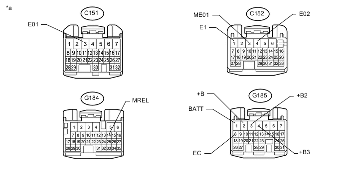
Text in Illustration *a Front view of wire harness connector
(to ECM)
- - -
Measure the resistance according to the value(s) in the table below.
Standard Resistance Tester Connection Condition Specified Condition C152-1 (E1) - Body ground Always Below 1 Ω C151-3 (E01) - Body ground Always Below 1 Ω C152-4 (E02) - Body ground Always Below 1 Ω C152-3 (ME01) - Body ground Always Below 1 Ω G185-8 (EC) - Body ground Always Below 1 Ω -
Measure the voltage according to the value(s) in the table below.
Standard Voltage Tester Connection Condition Specified Condition G185-1 (BATT) - Body ground Always 11 to 14 V G185-2 (+B) - Body ground Battery positive (+) voltage applied to terminal G184-14 (MREL) 11 to 14 V G185-3 (+B2) - Body ground Battery positive (+) voltage applied to terminal G184-14 (MREL) 11 to 14 V G185-4 (+B3) - Body ground Battery positive (+) voltage applied to terminal G184-14 (MREL) 11 to 14 V
-
-
for 2TR-FE:
-
Disconnect the C153, G180 and C181 ECM connectors.
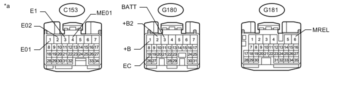
Text in Illustration *a Front view of wire harness connector
(to ECM)
- - -
Measure the resistance according to the value(s) in the table below.
Standard Resistance Tester Connection Condition Specified Condition C153-3 (E1) - Body ground Always Below 1 Ω C153-1 (E01) - Body ground Always Below 1 Ω C153-2 (E02) - Body ground Always Below 1 Ω C153-4 (ME01) - Body ground Always Below 1 Ω G180-18 (EC) - Body ground Always Below 1 Ω -
Measure the voltage according to the value(s) in the table below.
Standard Voltage Tester Connection Condition Specified Condition G180-3 (BATT) - Body ground Always 11 to 14 V G180-1 (+B) - Body ground Battery positive (+) voltage applied to terminal G181-6 (MREL) 11 to 14 V G180-2 (+B2) - Body ground Battery positive (+) voltage applied to terminal G181-6 (MREL) 11 to 14 V
Result Result Proceed to OK (for 1GR-FE) A OK (for 1KD-FTV) B OK (for 2TR-FE) C OK (for 1GD-FTV) D NG E -
A 
REPLACE ECM Click here
B
REPLACE ECM Click here
C
REPLACE ECM Click here
D
REPLACE ECM Click here
E
REPAIR OR REPLACE HARNESS OR CONNECTOR
-