CAN COMMUNICATION SYSTEM(for LHD with Entry and Start System) SYSTEM DIAGRAM
-
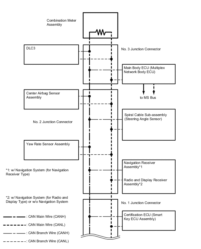
SYSTEM DIAGRAM
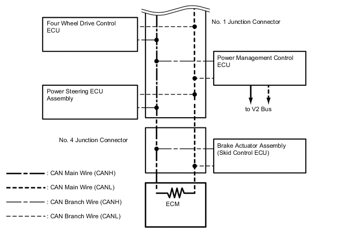
No. ECU/Sensor Name 1 ECM 2 Power management control ECU 3 Main body ECU (multiplex network body ECU) 4
-
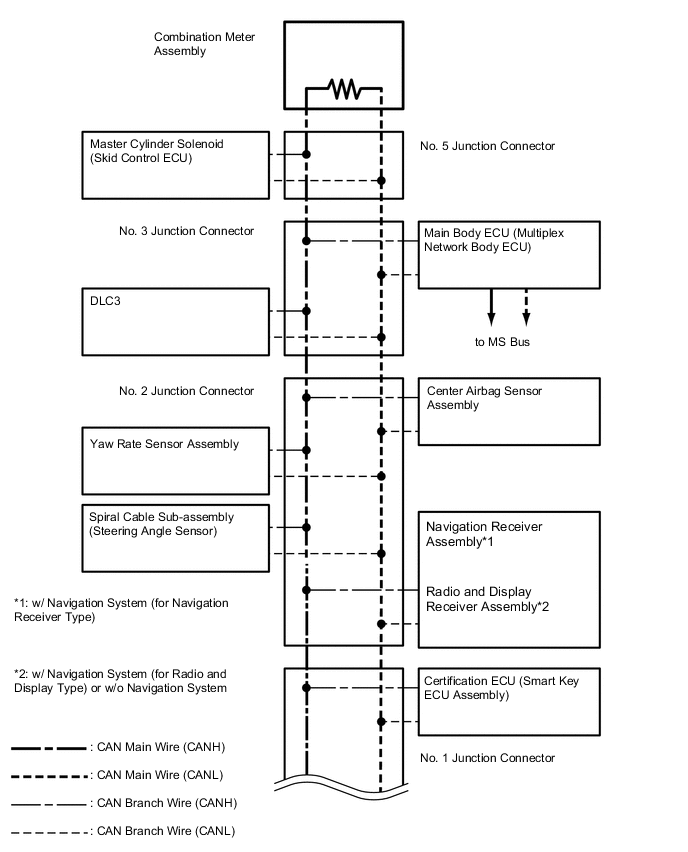
Master cylinder solenoid (skid control ECU)*1
-
Brake actuator assembly (skid control ECU)*2
5 Four wheel drive control ECU 6 Yaw rate sensor assembly 7 DLC3 8 Spiral cable sub-assembly (steering angle sensor) 9 Power steering ECU assembly 10
-
Navigation receiver assembly*3
-
Radio and display receiver assembly*4
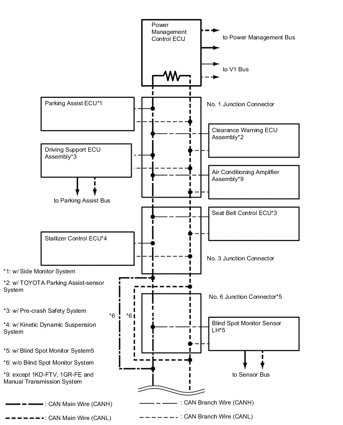
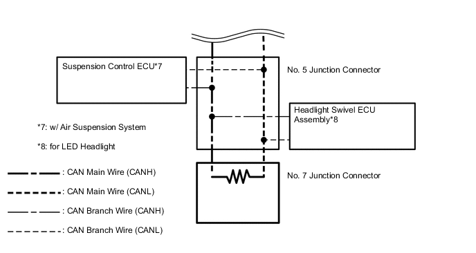
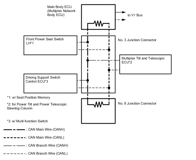
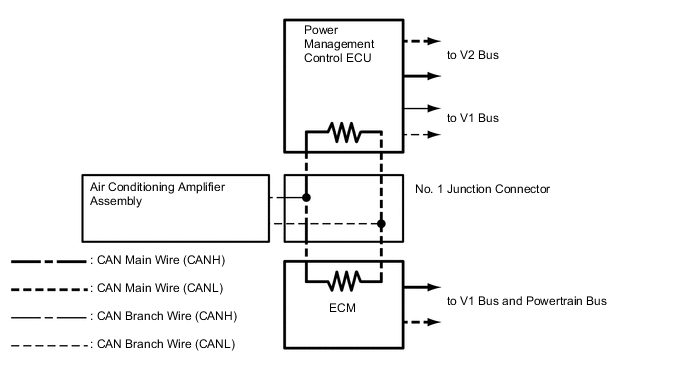
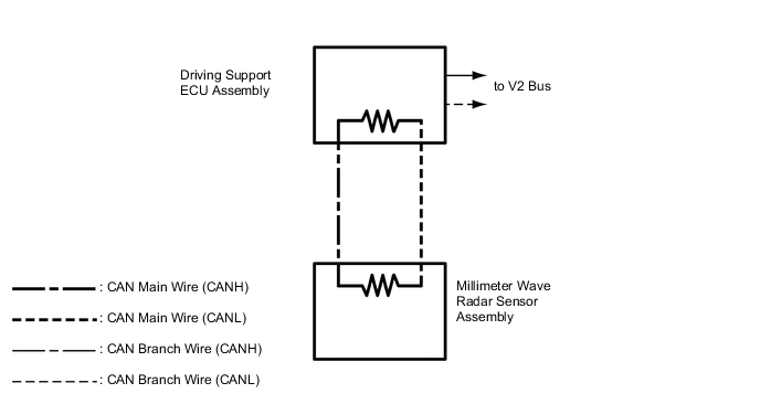
11 Certification ECU (smart key ECU assembly) 12 Center airbag sensor assembly 13 Combination meter assembly 14 Air conditioning amplifier assembly*16 15 Suspension control ECU*5 16 Headlight swivel ECU assembly*6 17 Seat belt control ECU*7 18 Stabilizer control ECU*8 19 Driving support ECU assembly*7 20 Parking assist ECU*9 21 Clearance warning ECU assembly*10 22 Blind spot monitor sensor LH*11 23 Blind spot monitor sensor RH*11 24 No. 7 junction connector 25 Front power seat switch LH*12 26 Multiplex tilt and telescopic ECU*13 27 Driving support switch control ECU*14 28 No. 8 junction connector 29 Transmission control ECU assembly*15 30 Millimeter wave radar sensor assembly*7 31 Air conditioning amplifier assembly*17 32 Nitrogen oxides sensor*18 33 Urea pump control ECU*18
-
*1: for 1GR-FE, 1KD-FTV, 1GD-FTV
-
*2: for 2TR-FE
-
*3: w/ Navigation System (for Navigation Receiver Type)
-
*4: w/ Navigation System (for Radio and Display Type) or w/o Navigation System
-
*5: w/ Air Suspension System
-
*6: for LED Headlight
-
*7: w/ Pre-crash Safety System
-
*8: w/ Kinetic Dynamic Suspension System
-
*9: w/ Side Monitor System
-
*10: w/ TOYOTA Parking Assist-sensor System
-
*11: w/ Blind Spot Monitor System
-
*12: w/ Seat Position Memory
-
*13: for Power Tilt and Power Telescopic Steering Column
-
*14: w/ Multi-function Switch
-
*15: for 1KD-FTV and Automatic Transmission System
-
*16: for 1KD-FTV, 1GR-FE and Manual Transmission System
-
*17: except 1KD-FTV, 1GR-FE and Manual Transmission System
-
*18: w/ Urea SCR System
-
-
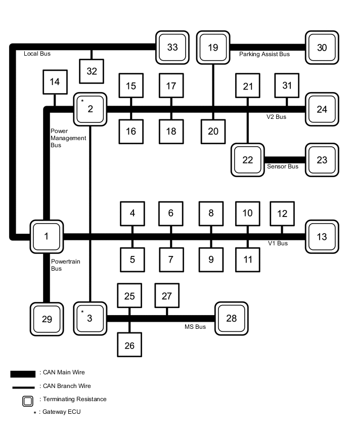
V1 BUS (for 1GR-FE, 1KD-FTV, 1GD-FTV)
-
V1 BUS (for 2TR-FE)
-
V2 BUS
-
MS BUS
-
POWER MANAGEMENT BUS (for 1KD-FTV, 1GR-FE and Manual Transmission System)
-
POWERTRAIN BUS (for 1KD-FTV and Automatic Transmission System)
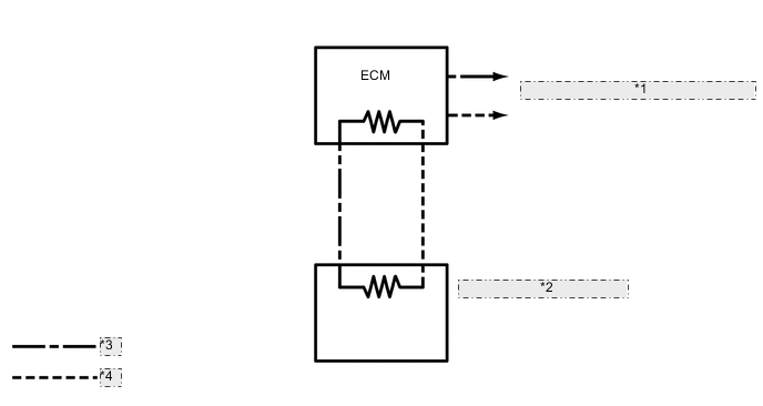
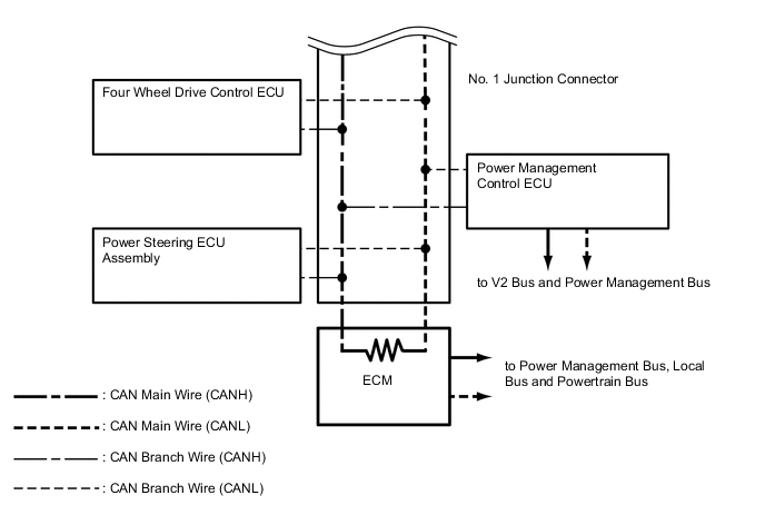
*1 to V1 Bus and Power Management Bus *2 Transmission Control ECU Assembly *3 CAN Main Wire (CANH) *4 CAN Main Wire (CANL) -
PARKING ASSIST BUS (w/ Pre-crash Safety System)
-
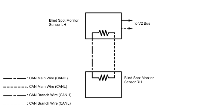
SENSOR BUS (w/ Blind Spot Monitor System)
-
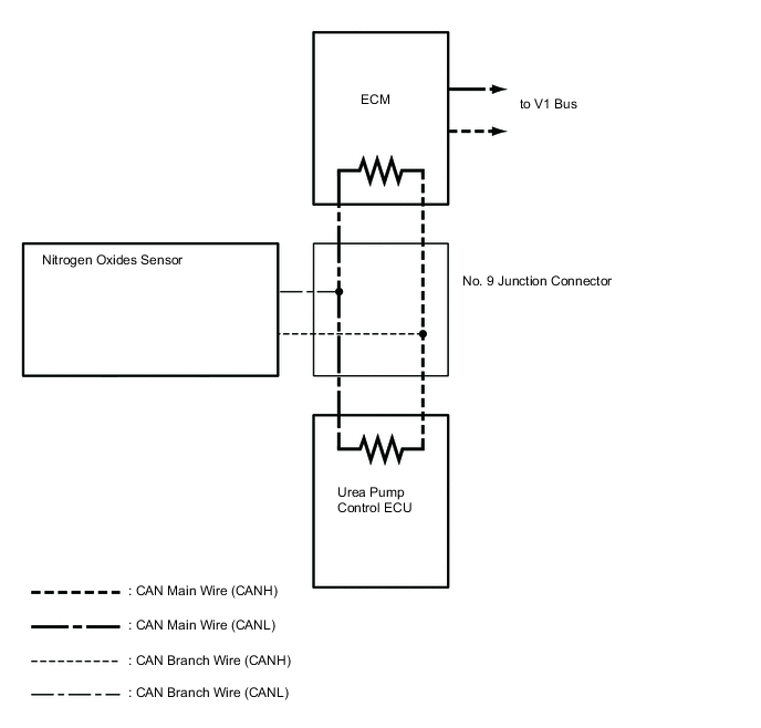
LOCAL BUS (w/ Urea SCR System)