CAN COMMUNICATION SYSTEM(for LHD with Entry and Start System), Diagnostic DTC:U010E/A2
| DTC Code | DTC Name |
|---|---|
| U010E/A2 | Lost Communication with Reductant Control Module |
DESCRIPTION
| DTC Code | DTC Detection Condition | Trouble Area |
|---|---|---|
| U010E/A2 | There is no communication from the urea pump control ECU. |
|
-
For vehicle with a urea SCR system.
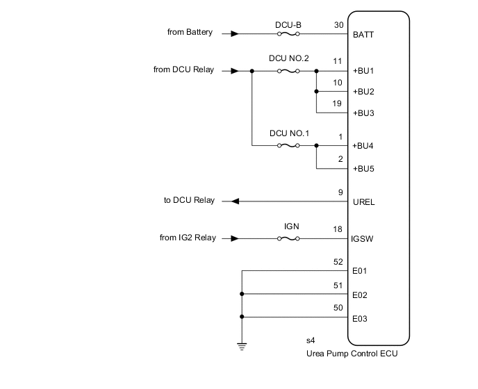
WIRING DIAGRAM
CAUTION / NOTICE / HINT
Note
Inspect the fuses for circuits related to this system before performing the following inspection procedure.
PROCEDURE
-
CHECK HARNESS AND CONNECTOR (UREA PUMP CONTROL ECU - BATTERY AND BODY GROUND)
-
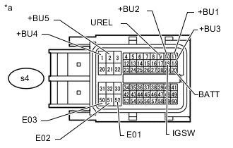
Text in Illustration *a Front view of wire harness connector
(to Urea Pump Control ECU)
Disconnect the urea pump control ECU connector.
-
Measure the resistance according to the value(s) in the table below.
Standard Resistance Tester Connection Condition Specified Condition s4-52 (E01) - Body ground Always Below 1 Ω s4-51 (E02) - Body ground Always Below 1 Ω s4-50 (E03) - Body ground Always Below 1 Ω -
Measure the voltage according to the value(s) in the table below.
Standard Voltage Tester Connection Condition Specified Condition s4-30 (BATT) - Body ground Always 11 to 14 V s4-11 (+BU1) - Body ground Battery positive (+) voltage applied to terminal s4-9 (UREL) 11 to 14 V s4-10 (+BU2) - Body ground Battery positive (+) voltage applied to terminal s4-9 (UREL) 11 to 14 V s4-19 (+BU3) - Body ground Battery positive (+) voltage applied to terminal s4-9 (UREL) 11 to 14 V s4-1 (+BU4) - Body ground Battery positive (+) voltage applied to terminal s4-9 (UREL) 11 to 14 V s4-2 (+BU5) - Body ground Battery positive (+) voltage applied to terminal s4-9 (UREL) 11 to 14 V s4-18 (IGSW) - Body ground Engine switch on (IG) 11 to 14 V
OK 
REPLACE UREA PUMP CONTROL ECU Click here
NG
REPAIR OR REPLACE HARNESS OR CONNECTOR
-