INTEGRATION RELAY INSTALLATION
CAUTION / NOTICE / HINT
Tech Tips
-
Use the same procedure for RHD and LHD vehicles.
-
The procedure listed below is for LHD vehicles.
PROCEDURE
-
INSTALL NO. 1 INTEGRATION RELAY
-
except 5L-E:
-
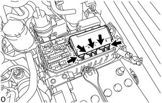
Connect the 5 connectors.
Note
-
Make sure that the connectors are vertically inserted into the No. 1 integration relay. Additionally, when the connectors cannot be inserted properly, do not force or twist them into the socket.
-
Do not drop the No. 1 integration relay or subject it to any strong impacts. Additionally, do not use a No. 1 integration relay that has been dropped.
-
-
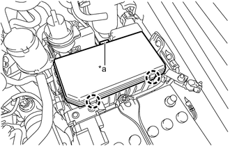
*a No. 1 Integration Relay Fixing Lock While pushing the No. 1 integration relay fixing lock shown in the illustration toward the center, push the No. 1 integration relay down to install it.
Note
-
When installing the No. 1 integration relay to the engine room relay block, do not strike the head of the No. 1 integration relay with heavy objects. Additionally, do not push on the fuses during installation.
-
Check that the installation area of the engine room relay block and No. 1 integration relay are properly connected.
-
-
-
for 5L-E:
-
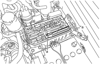
Attach the 2 claws to install the No. 1 integration relay to the engine room junction block.
-
-
-
INSTALL NO. 1 RELAY BLOCK COVER
-
*a Lock Hook the 2 claws of the No. 1 relay block cover onto the engine room relay block.
-
Attach the claws of the No. 1 relay block cover lock to install the No. 1 relay block cover.
-
-
CONNECT CABLE TO NEGATIVE BATTERY TERMINAL
Note
When disconnecting the cable, some systems need to be initialized after the cable is reconnected.