MAIN BODY ECU REMOVAL
CAUTION / NOTICE / HINT
Note
Do not remove the main body ECU (multiplex network body ECU) except when replacing it.
Tech Tips
-
Use the same procedure for RHD and LHD vehicles.
-
The procedure listed below is for LHD vehicles.
PROCEDURE
-
DISCONNECT DISCHARGE DOOR CONTROL BATTERY AND DISCONNECT CABLE FROM NEGATIVE BATTERY TERMINAL (w/ Door Control Battery)
Tech Tips
-
When the door control battery becomes completely discharged and the power supply is cut, the multiplex network body ECU (main body ECU) communication lost error "Lost communication with vehicle" appears on the GTS display.
-
The number of times the Active Test can be performed depends on the charge condition of the door control battery.
CAUTION:
Wait at least 90 seconds after disconnecting the cable from the negative (-) battery terminal to disable the SRS system.
Note
-
After turning the ignition switch off, waiting time may be required before disconnecting the cable from the battery terminal. Therefore, make sure to read the disconnecting the cable from the battery terminal notice before proceeding with work.
-
When disconnecting the cable, some systems need to be initialized after the cable is reconnected.
-
Make sure to perform this procedure with the power supply of the battery and door control battery cut to prevent damage during removal and installation of the instrument panel junction block assembly.
-
Make sure to perform the following procedures, and then perform removal and installation of the instrument panel junction block assembly with the power supply from the battery and door control battery cut.
-
Turn the ignition switch off.
-
Connect the GTS to the DLC3.
-
Turn the GTS on.
-
Enter the following menus: Body Electrical / Main Body / Active Test.
Body Electrical / Main Body / Active Test Tester Display Control Range Shock Detection Unlock UNLOCK/LOCK Note
Do not perform the Active Test at this time.
-
Disconnect the cable from the negative (-) battery terminal.
-
Repeat the "Shock Detection Unlock" Active Test until the multiplex network body ECU (main body ECU) communication lost error "Lost communication with vehicle" appears on the GTS display.
Body Electrical / Main Body / Active Test Tester Display Shock Detection Unlock Tech Tips
-
When the door control battery becomes completely discharged and the power supply is cut, the multiplex network body ECU (main body ECU) communication lost error "Lost communication with vehicle" appears on the GTS display.
-
The number of times the Active Test can be performed depends on the charge condition of the door control battery.
-
-
-
DISCONNECT CABLE FROM NEGATIVE BATTERY TERMINAL (w/o Door Control Battery)
CAUTION:
Wait at least 90 seconds after disconnecting the cable from the negative (-) battery terminal to disable the SRS system.
Note
-
After turning the ignition switch off, waiting time may be required before disconnecting the cable from the battery terminal. Therefore, make sure to read the disconnecting the cable from the battery terminal notice before proceeding with work.
-
When disconnecting the cable, some systems need to be initialized after the cable is reconnected.
-
-
REMOVE FRONT FLOOR FOOTREST (for LHD)
-
REMOVE DOOR SCUFF PLATE ASSEMBLY LH
-
REMOVE COWL SIDE TRIM BOARD LH
-
REMOVE NO. 1 INSTRUMENT PANEL UNDER COVER SUB-ASSEMBLY
-
REMOVE FRONT DOOR OPENING TRIM WEATHERSTRIP LH
-
REMOVE INSTRUMENT SIDE PANEL LH
-
REMOVE LOWER INSTRUMENT PANEL FINISH PANEL SUB-ASSEMBLY
-
REMOVE LOWER NO. 1 INSTRUMENT PANEL AIRBAG ASSEMBLY (w/ Knee Airbag)
-
REMOVE DRIVER SIDE JUNCTION BLOCK ASSEMBLY WITH MAIN BODY ECU (for LHD, except 5L-E)
-

Connector (A) 
Connector (B) for Type A:
-
Disconnect the 2 connectors (A) and connector (B).
-
-
for Type B:
-
Disconnect the 2 connectors (A).
-
-
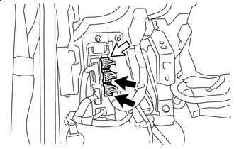
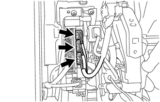
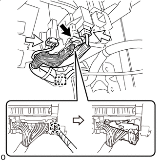
Lever Connector Connector (A) 
Connector (B) 
Protective Tape Disconnect the 2 connectors (A).
-
w/ Door Control Battery:
-
Disconnect the connector (B).
-
-
Using a thin-bladed screwdriver with its tip wrapped with protective tape, detach the claw and disconnect the 2 lever connectors.
-
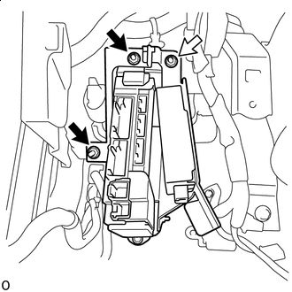
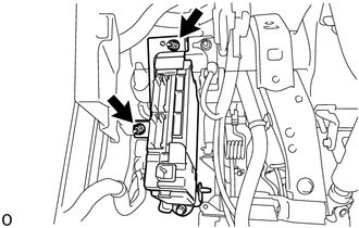
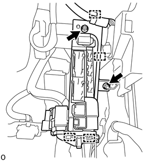
Nut (A) Nut (B) Remove the 2 nuts (A).
-
w/ Door Control Battery:
-
Remove the 2 nuts (A) and nut (B).
-
-
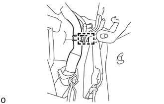
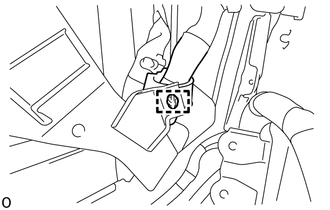
Detach the clamp.
-
Detach the clamp.
-
Detach the clamp.
-
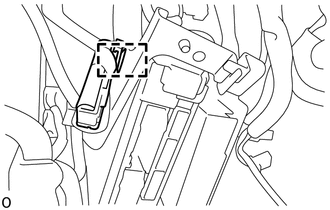
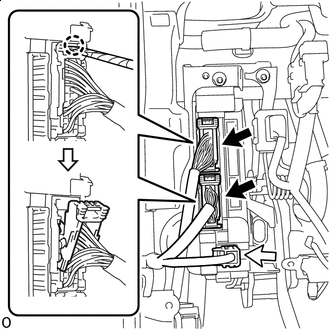
Protective Tape Using a thin-bladed screwdriver with its tip wrapped with protective tape, detach the claw and disconnect the lever connector.
-
Protective Tape Using a thin-bladed screwdriver with its tip wrapped with protective tape, detach the claw and disconnect the lever connector and then remove the driver side junction block assembly with the main body ECU.
-
-
REMOVE DRIVER SIDE JUNCTION BLOCK ASSEMBLY WITH MAIN BODY ECU (for LHD, 5L-E)
-
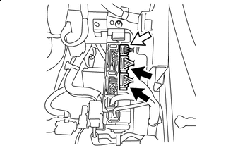
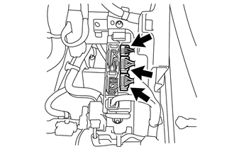
Disconnect the 3 connectors.
-
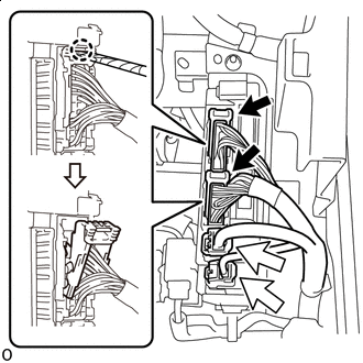
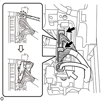
Lever Connector Connector Protective Tape Disconnect the connector.
-
Using a thin-bladed screwdriver with its tip wrapped with protective tape, detach the claw and disconnect the 2 lever connectors.
-
Remove the 2 nuts.
-
Detach the clamp.
-
Detach the clamp.
-
Detach the clamp.
-
Protective Tape Using a thin-bladed screwdriver with its tip wrapped with protective tape, detach the claw and disconnect the lever connector.
-
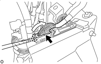
Detach the claw and release the connector's lock as shown in the illustration.
-
Protective Tape Using a thin-bladed screwdriver with its tip wrapped with protective tape, detach the claw and disconnect the lever connector and then remove the driver side junction block assembly with the main body ECU.
-
-
REMOVE DRIVER SIDE JUNCTION BLOCK ASSEMBLY WITH MAIN BODY ECU (for RHD, except 5L-E)
-
Connector (A) Connector (B) for Type A:
-
Disconnect the 2 connectors (A) and connector (B).
-
-
for Type B:
-
Disconnect the 2 connectors (A).
-
-
Lever Connector Connector Protective Tape Disconnect the 2 connectors.
-
Using a thin-bladed screwdriver with its tip wrapped with protective tape, detach the claw and disconnect the 2 lever connectors.
-
Lever Connector Connector Protective Tape Disconnect the 2 connectors.
-
Using a thin-bladed screwdriver with its tip wrapped with protective tape, detach the claw and disconnect the lever connector.
-
Detach the clamp.
-
Remove the 2 nuts.
-
Detach the 4 clamps.
-
w/ KDSS:
-
Remove the stabilizer control ECU.
-
-
Detach the clamp.
-
Detach the clamp.
-
Protective Tape Using a thin-bladed screwdriver with its tip wrapped with protective tape, detach the claw and disconnect the lever connector.
-
Protective Tape Using a thin-bladed screwdriver with its tip wrapped with protective tape, detach the claw and disconnect the lever connector and then remove the driver side junction block assembly with the main body ECU.
-
-
REMOVE DRIVER SIDE JUNCTION BLOCK ASSEMBLY WITH MAIN BODY ECU (for RHD, 5L-E)
-
Disconnect the 3 connectors.
-
Lever Connector Connector Protective Tape Disconnect the connector.
-
Using a thin-bladed screwdriver with its tip wrapped with protective tape, detach the claw and disconnect the 2 lever connectors.
-
Lever Connector Connector Protective Tape Disconnect the 2 connectors.
-
Using a thin-bladed screwdriver with its tip wrapped with protective tape, detach the claw and disconnect the lever connector.
-
Detach the clamp.
-
Remove the 2 nuts.
-
Detach the 4 clamps.
-
Detach the clamp.
-
Detach the clamp.
-
Protective Tape Using a thin-bladed screwdriver with its tip wrapped with protective tape, detach the claw and disconnect the lever connector.
-
Detach the claw and release the connector's lock as shown in the illustration.
-
Protective Tape Using a thin-bladed screwdriver with its tip wrapped with protective tape, detach the claw and disconnect the lever connector and then remove the driver side junction block assembly with the main body ECU.
-
-
REMOVE DOOR CONTROL BATTERY (w/ Door Control Battery)
-
REMOVE MAIN BODY ECU (MULTIPLEX NETWORK BODY ECU)
-
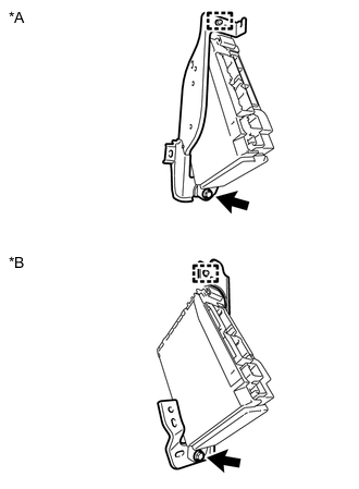
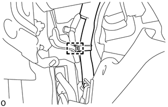
*A for LHD *B for RHD Remove the bolt.
-
Detach the guide and remove the wiring harness clamp bracket.
-
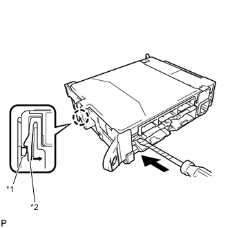
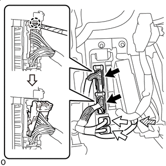
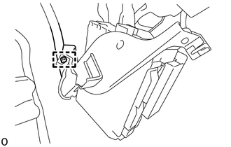
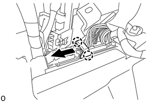
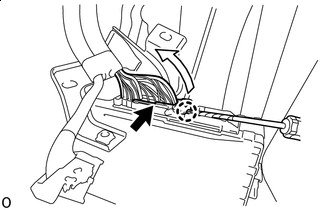
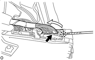
*1 Main Body ECU (Multiplex Network Body ECU) *2 Driver Side Junction Block Assembly Protective Tape Press the claw of the driver side junction block assembly as shown in the illustration to release the lock.
-
With the driver side junction block assembly lock released, insert a screwdriver with its tip wrapped with protective tape horizontally between the main body ECU (multiplex network body ECU) and driver side junction block assembly.
Note
-
Use a screwdriver with a diameter between 5.0 mm (0.197 in.) and 6.3 mm (0.248 in.) and a length of approximately 90 mm (3.54 in.).
-
Do not insert the screwdriver under the connector socket of the driver side junction block assembly or the main body ECU (multiplex network body ECU).
-
-
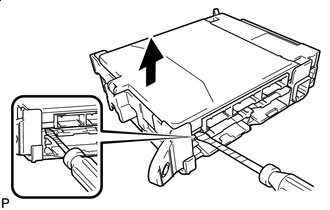
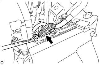
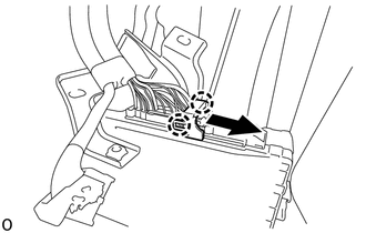
Protective Tape Using a screwdriver, carefully raise the main body ECU (multiplex network body ECU) to the position where the connector becomes disconnected.
Note
-
Do not twist the screwdriver to raise the main body ECU (multiplex network body ECU).
-
Replace the driver side junction block assembly or the main body ECU (multiplex network body ECU) when the connector terminal, locking section or case is damaged or deformed.
-
-
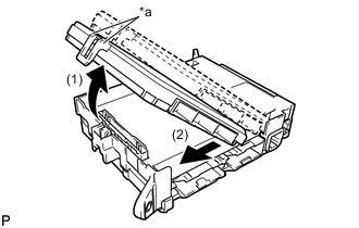
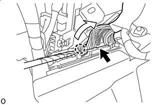
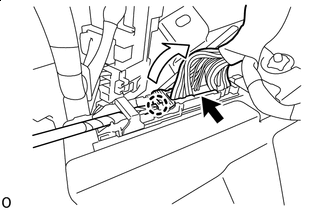
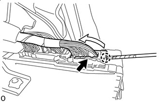
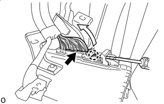
*a Rib Catch hold rib of ECU's lock and raise the main body ECU (multiplex network body ECU) as shown by the arrow (1), and then pull it out as shown by the arrow (2) in the illustration.
Note
-
Do not touch the driver side junction block assembly connector or the main body ECU (multiplex network body ECU) connector.
-
When removing the driver side junction block assembly or the main body ECU (multiplex network body ECU), take care not to damage it.
-
Do not use the driver side junction block assembly or the main body ECU (multiplex network body ECU) that has been dropped or subjected to a strong shock.
-
-