CLEARANCE SONAR MAIN SWITCH INSPECTION
PROCEDURE
-
INSPECT BACK SONAR OR CLEARANCE SONAR SWITCH ASSEMBLY
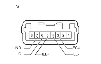
Text in Illustration *a Component without harness connected
(Back Sonar or Clearance Sonar Switch)
-
Check the resistance.
-
Measure the resistance according to the value(s) in the table below.
Standard Resistance Tester Connection Switch Condition Specified Condition 3 (ECU) - 6 (IG) Sonar switch off 10 kΩ or higher Sonar switch on Below 1 Ω If the result is not as specified, replace the back sonar or clearance sonar switch.
-
-
Inspect the indicator operation.
OK Measurement Condition Specified Condition Battery positive (+) → Terminal 3 (ECU)
Battery negative (-) → Terminal 7 (IND)
LED illuminates If the result is not as specified, replace the back sonar or clearance sonar switch.
-
Inspect the illumination operation.
OK Measurement Condition Specified Condition Battery positive (+) → Terminal 5 (ILL+)
Battery negative (-) → Terminal 4 (ILL-)
LED illuminates If the result is not as specified, replace the back sonar or clearance sonar switch.
-