CLEARANCE WARNING INDICATOR INSPECTION
PROCEDURE
-
INSPECT HAZARD WARNING SIGNAL SWITCH ASSEMBLY (CLEARANCE WARNING INDICATOR)
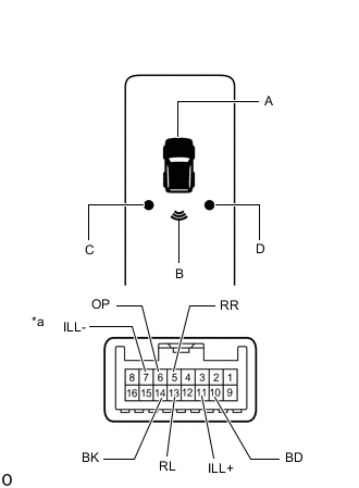
*a Component without harness connected
(Clearance Warning Indicator Assembly)
-
Inspect the indicator operation.
-
for A:
OK Measurement Condition Specified Condition Battery positive (+) → Terminal 10 (BD)
Battery negative (-) → Terminal 6 (OP)
LED illuminates If the result is not as specified, replace the hazard warning signal switch assembly (clearance warning indicator).
-
for B:
OK Measurement Condition Specified Condition Battery positive (+) → Terminal 10 (BD)
Battery negative (-) → Terminal 14 (BK)
LED illuminates If the result is not as specified, replace the hazard warning signal switch assembly (clearance warning indicator).
-
for C:
OK Measurement Condition Specified Condition Battery positive (+) → Terminal 10 (BD)
Battery negative (-) → Terminal 13 (RL)
LED illuminates If the result is not as specified, replace the hazard warning signal switch assembly (clearance warning indicator).
-
for D:
OK Measurement Condition Specified Condition Battery positive (+) → Terminal 10 (BD)
Battery negative (-) → Terminal 5 (RR)
LED illuminates If the result is not as specified, replace the hazard warning signal switch assembly (clearance warning indicator).
-
-
Inspect the illumination operation.
OK Measurement Condition Specified Condition Battery positive (+) → Terminal 11 (ILL+)
Battery negative (-) → Terminal 7 (ILL-)
LED illuminates If the result is not as specified, replace the hazard warning signal switch assembly (clearance warning indicator).
-