MULTI-TERRAIN MONITOR SYSTEM, Diagnostic DTC:C1625
| DTC Code | DTC Name |
|---|---|
| C1625 | Open or Short in Steering Angle Sensor +B |
DESCRIPTION
This DTC is stored if the parking assist ECU receives a signal via CAN communication from the steering sensor that indicates a power supply system problem.
| DTC Code | DTC Detection Condition | Trouble Area |
|---|---|---|
| C1625 | Open or short in steering angle sensor +B |
|
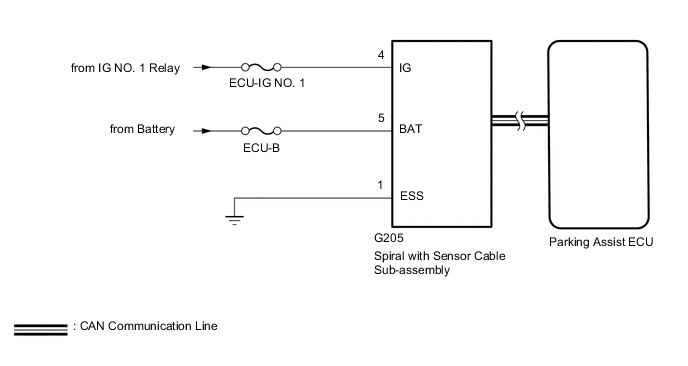
WIRING DIAGRAM
CAUTION / NOTICE / HINT
Note
-
When "!" mark is displayed on the navigation receiver assembly*1 or radio and display receiver assembly*2 after the cable is disconnected from the negative (-) battery terminal, correct the steering angle neutral point.
-
*1: for Navigation Receiver Type
-
*2: for Radio and Display Type
-
Depending on the parts that are replaced or operations that are performed during vehicle inspection or maintenance, calibration of other systems as well as the multi-terrain monitor system may be needed Click here.
-
The vehicle is equipped with a Supplemental Restraint System (SRS) which includes components such as airbags.
Before servicing (including removal or installation of parts), be sure to read the precaution for Supplemental Restraint System Click here.
-
After turning the engine switch off, waiting time may be required before disconnecting the cable from the negative (-) battery terminal. Therefore, make sure to read the disconnecting the cable from the negative (-) battery terminal notices before proceeding with work.
-
Inspect the fuses for circuits related to this system before performing the following procedure.
PROCEDURE
-
CHECK HARNESS AND CONNECTOR (SPIRAL WITH SENSOR CABLE SUB-ASSEMBLY - BATTERY AND BODY GROUND)
-
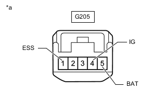
*a Front view of wire harness connector
(to Spiral with Sensor Cable Sub-assembly)
Disconnect the spiral with sensor cable sub-assembly connector.
-
Measure the resistance according to the value(s) in the table below.
Standard Resistance Tester Connection Condition Specified Condition G205-1 (ESS) - Body ground Always Below 1 Ω -
Measure the voltage according to the value(s) in the table below.
Standard Voltage Tester Connection Condition Specified Condition G205-4 (IG) - G205-1 (ESS) Engine switch on (IG) 11 to 14 V G205-5 (BAT) - G205-1 (ESS) Always 11 to 14 V
OK 
REPLACE SPIRAL WITH SENSOR CABLE SUB-ASSEMBLY Click here
NG
REPAIR OR REPLACE HARNESS OR CONNECTOR
-