MULTI-TERRAIN MONITOR SYSTEM, Diagnostic DTC:C1681
| DTC Code | DTC Name |
|---|---|
| C1681 | Front Camera Feedback Malfunction |
DESCRIPTION
DTC C1681 is stored if the parking assist ECU judges as a result of ifs self check that a synchronization problem is occurring in the image signal sent from the front television camera assembly to the parking assist ECU.
| DTC Code | DTC Detection Condition | Trouble Area |
|---|---|---|
| C1681 | Front television camera power supply failure |
|
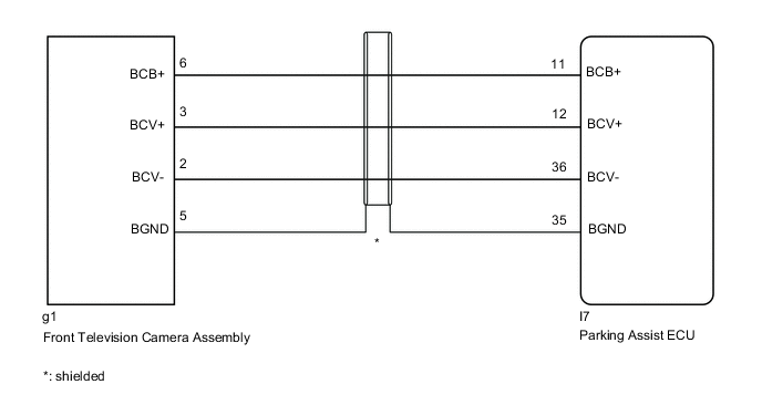
WIRING DIAGRAM
CAUTION / NOTICE / HINT
Note
-
When "!" mark is displayed on the navigation receiver assembly*1 or radio and display receiver assembly*2 after the cable is disconnected from the negative (-) battery terminal, correct the steering angle neutral point.
-
*1: for Navigation Receiver Type
-
*2: for Radio and Display Type
-
Depending on the parts that are replaced or operations that are performed during vehicle inspection or maintenance, calibration of other systems as well as multi-terrain monitor system may be needed Click here.
PROCEDURE
-
CHECK HARNESS AND CONNECTOR (PARKING ASSIST ECU - FRONT TELEVISION CAMERA ASSEMBLY)
-
Disconnect the I7 parking assist ECU connector.
-
Disconnect the g1 front television camera assembly connector.
-
Measure the resistance according to the value(s) in the table below.
Standard Resistance Tester Connection Condition Specified Condition I7-36 (BCV-) - g1-2 (BCV-) Always Below 1 Ω I7-12 (BCV+) - g1-3 (BCV+) Always Below 1 Ω I7-35 (BGND) - g1-5 (BGND) Always Below 1 Ω I7-11 (BCB+) - g1-6 (BCB+) Always Below 1 Ω I7-36 (BCV-) - Body ground Always 10 kΩ or higher I7-12 (BCV+) - Body ground Always 10 kΩ or higher I7-35 (BGND) - Body ground Always 10 kΩ or higher I7-11 (BCB+) - Body ground Always 10 kΩ or higher
NG 
REPAIR OR REPLACE HARNESS OR CONNECTOR
OK 
-
-
CHECK PARKING ASSIST ECU (BCV-, BGND)
-
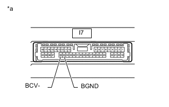
*a Component without harness connected
(Parking Assist ECU)
Disconnect the parking assist ECU connector.
-
Measure the resistance according to the value(s) in the table below.
Standard Resistance Tester Connection Condition Specified Condition 35 (BGND) - Body ground Always Below 1 Ω 36 (BCV-) - Body ground Always Below 1 Ω
NG
REPLACE PARKING ASSIST ECU for LHD: REPLACE PARKING ASSIST ECU Click here
REPLACE PARKING ASSIST ECU for RHD: REPLACE PARKING ASSIST ECU Click hereOK
-
-
CHECK PARKING ASSIST ECU (BCB+, BGND)
-
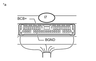
*a Component with harness connected
(Parking Assist ECU)
Disconnect the front television camera assembly connector.
-
Measure the voltage according to the value(s) in the table below.
Standard Voltage Tester Connection Switch Condition Specified Condition I7-11 (BCB+) - I7-35 (BGND) Engine switch on (IG) 5.5 to 7.05 V I7-11 (BCB+) - I7-35 (BGND) Engine switch off Below 1 V
NG
REPLACE PARKING ASSIST ECU for LHD: REPLACE PARKING ASSIST ECU Click here
REPLACE PARKING ASSIST ECU for RHD: REPLACE PARKING ASSIST ECU Click hereOK
-
-
CHECK FRONT TELEVISION CAMERA ASSEMBLY (BCV+, BGND)
-
Check the wave form of the front television camera assembly using an oscilloscope.
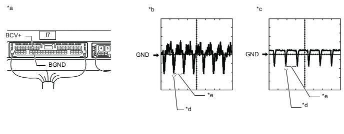
Text in Illustration *a Component with harness connected
(Parking Assist ECU)
*b Waveform A *c Waveform B *d Synchronization Signal *e Video Waveform - - Tech Tips
The video waveform changes according to the image sent by the front television camera assembly.
Item Content Terminal No. (Symbol) I7-12 (BCV+) - I7-35 (BGND) Tool Setting 200 mV/DIV., 50 μsec./DIV. Condition
-
Waveform A: Engine switch on (IG), panoramic view monitor switch (multi-terrain monitor switch) on and camera lens is not covered, displaying an image
-
Waveform B: Engine switch on (IG), panoramic view monitor switch (multi-terrain monitor switch) on and camera lens is covered, blacking out the screen
OK Waveform is as shown in the illustration. -
OK
REPLACE PARKING ASSIST ECU for LHD: REPLACE PARKING ASSIST ECU Click here
REPLACE PARKING ASSIST ECU for RHD: REPLACE PARKING ASSIST ECU Click hereNG
REPLACE FRONT TELEVISION CAMERA ASSEMBLY Click here
-