MULTI-TERRAIN MONITOR SYSTEM, Diagnostic DTC:U0265, U0266, U0267, U0268
| DTC Code | DTC Name |
|---|---|
| U0265 | Lost Communication with Image Processing Sensor A |
| U0266 | Lost Communication with Image Processing Sensor B |
| U0267 | Lost Communication with Image Processing Sensor C |
| U0268 | Lost Communication with Image Processing Sensor D |
DESCRIPTION
| DTC Code | DTC Detection Condition | Trouble Area |
|---|---|---|
| U0265 | Lost Communication with rear television camera assembly |
|
| U0266 | Lost Communication with side television camera assembly LH |
|
| U0267 | Lost Communication with front television camera assembly |
|
| U0268 | Lost Communication with side television camera assembly RH |
|
WIRING DIAGRAM

CAUTION / NOTICE / HINT
Note
-
Before measuring the resistance of the CAN bus, turn the engine switch off and leave the vehicle for 1 minute or more without operating the key, switches or opening or closing the doors. After that, disconnect the cable from the negative (-) battery terminal and leave the vehicle for 1 minute or more before measuring the resistance.
-
After turning the engine switch off, waiting time may be required before disconnecting the cable from the battery terminal. Therefore, make sure to read the disconnecting the cable from the battery terminal notice before proceeding with work
Tech Tips
-
Operating the engine switch, any other switches or a door triggers related ECU and sensor communication on the CAN. This communication will cause the resistance value to change.
-
Even after DTCs are cleared, if a DTC is stored again after driving the vehicle for a while, the malfunction may be occurring due to vibration of the vehicle. In such a case, wiggling the ECUs or wire harness while performing the inspection below may help determine the cause of the malfunction.
PROCEDURE
-
CHECK DTC OUTPUT
-
Clear the DTCs.
-
Recheck for DTCs and check that no DTCs are output.
Result Result Proceed to DTC U0265, U0266, U0267, and U0268 are not output. A DTC U0265 are output. B DTC U0266 are output. C DTC U0267 are output. D DTC U0268 are output. E DTC U0265, U0266, U0267, and U0268 are output. F
A 
USE SIMULATION METHOD TO CHECK Click here
C 
CHECK FOR OPEN IN CAN BUS WIRE (OUTER REAR VIEW MIRROR ASSEMBLY LH BRANCH WIRE) Click here
D
CHECK FOR OPEN IN CAN BUS WIRE (FRONT TELEVISION CAMERA ASSEMBLY BRANCH WIRE) Click here
E
CHECK FOR OPEN IN CAN BUS WIRE (OUTER REAR VIEW MIRROR ASSEMBLY RH BRANCH WIRE) Click here
F
CHECK CAN BUS WIRE Click here
B 
-
-
CHECK FOR OPEN IN CAN BUS WIRE (REAR TELEVISION CAMERA ASSEMBLY BRANCH WIRE)
-
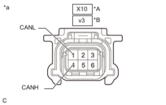
*A w/o Tire Carrier *B w/ Tire Carrier *a Front view of wire harness connector
(to Rear Television Camera Assembly)
Disconnect the cable from the negative (-) battery terminal.
-
Disconnect the rear television camera assembly connector.
-
Measure the resistance according to the value(s) in the table below.
Standard Resistance w/o Tire Carrier Tester Connection Condition Specified Condition X10-4 (CANH) - X10-1 (CANL) Cable disconnected from negative (-) battery terminal 54 to 69 Ω w/ Tire Carrier Tester Connection Condition Specified Condition v3-4 (CANH) - v3-1 (CANL) Cable disconnected from negative (-) battery terminal 54 to 69 Ω Result Proceed to OK NG
OK
REPLACE REAR TELEVISION CAMERA ASSEMBLY w/ Tire Carrier: Click here
REPLACE REAR TELEVISION CAMERA ASSEMBLY w/o Tire Carrier: Click hereNG
REPAIR OR REPLACE CAN BUS BRANCH WIRE OR CONNECTOR
-
-
CHECK FOR OPEN IN CAN BUS WIRE (OUTER REAR VIEW MIRROR ASSEMBLY LH BRANCH WIRE)
-
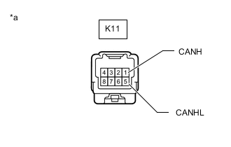
*a Front view of wire harness connector
(to Outer Rear View Mirror Assembly LH)
Disconnect the cable from the negative (-) battery terminal.
-
Disconnect the outer rear view mirror assembly LH connector.
-
Measure the resistance according to the value(s) in the table below.
Standard Resistance Tester Connection Condition Specified Condition K11-1 (CANH) - K11-5 (CANL) Cable disconnected from negative (-) battery terminal 54 to 69 Ω Result Proceed to OK NG
NG
REPAIR OR REPLACE CAN BUS BRANCH WIRE OR CONNECTOR
OK
-
-
CHECK FOR OPEN IN CAN BUS WIRE (SIDE TELEVISION CAMERA ASSEMBLY LH BRANCH WIRE)
-

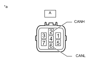
*a Front view of wire harness connector
(to Side Television Camera Assembly LH)
Reconnect the outer rear view mirror assembly LH connector.
-
Disconnect the side television camera assembly LH connector.
-
Measure the resistance according to the value(s) in the table below.
Standard Resistance Tester Connection Condition Specified Condition B-2 (CANH) - B-6 (CANL) Cable disconnected from negative (-) battery terminal 54 to 69 Ω Result Proceed to OK NG
OK
REPLACE SIDE TELEVISION CAMERA ASSEMBLY LH Click here
NG
REPLACE OUTER REAR VIEW MIRROR ASSEMBLY LH Click here
-
-
CHECK FOR OPEN IN CAN BUS WIRE (FRONT TELEVISION CAMERA ASSEMBLY BRANCH WIRE)
-
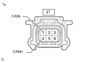
*a Front view of wire harness connector
(to Rear Television Camera Assembly)
Disconnect the cable from the negative (-) battery terminal.
-
Disconnect the front television camera assembly connector.
-
Measure the resistance according to the value(s) in the table below.
Standard Resistance Tester Connection Condition Specified Condition g1-4 (CANH) - g1-1 (CANL) Cable disconnected from negative (-) battery terminal 54 to 69 Ω Result Proceed to OK NG
OK
REPLACE FRONT TELEVISION CAMERA ASSEMBLY Click here
NG
REPAIR OR REPLACE CAN BUS BRANCH WIRE OR CONNECTOR
-
-
CHECK FOR OPEN IN CAN BUS WIRE (OUTER REAR VIEW MIRROR ASSEMBLY RH BRANCH WIRE)
-
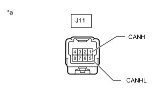
*a Front view of wire harness connector
(to Outer Rear View Mirror Assembly RH)
Disconnect the cable from the negative (-) battery terminal.
-
Disconnect the outer rear view mirror assembly RH connector.
-
Measure the resistance according to the value(s) in the table below.
Standard Resistance Tester Connection Condition Specified Condition J11-1 (CANH) - J11-5 (CANL) Cable disconnected from negative (-) battery terminal 54 to 69 Ω Result Proceed to OK NG
NG
REPAIR OR REPLACE CAN BUS BRANCH WIRE OR CONNECTOR
OK
-
-
CHECK FOR OPEN IN CAN BUS WIRE (SIDE TELEVISION CAMERA ASSEMBLY RH BRANCH WIRE)
-
*a Front view of wire harness connector
(to Side Television Camera Assembly RH)
Reconnect the outer rear view mirror assembly RH connector.
-
Disconnect the side television camera assembly RH connector.
-
Measure the resistance according to the value(s) in the table below.
Standard Resistance Tester Connection Condition Specified Condition A-2 (CANH) - A-6 (CANL) Cable disconnected from negative (-) battery terminal 54 to 69 Ω Result Proceed to OK NG
OK
REPLACE SIDE TELEVISION CAMERA ASSEMBLY RH Click here
NG
REPLACE OUTER REAR VIEW MIRROR ASSEMBLY RH Click here
-
-
CHECK CAN BUS WIRE
-
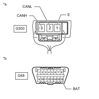
*a Component with harness connected
(CAN Junction Terminal)
*b Front view of DLC3 Disconnect the cable from the negative (-) battery terminal.
-
Measure the resistance according to the value(s) in the table below.
Standard Resistance Tester Connection Condition Specified Condition Resistance: Malfunction G300-3 (CANH) - G300-2 (CANL) Cable disconnected from negative (-) battery terminal 54 to 69 Ω Below 53 Ω: Short in line G300-3 (CANH) - G300-2 (CANL) Cable disconnected from negative (-) battery terminal 54 to 69 Ω Higher than 70 Ω: Open in CAN main bus line G300-3 (CANH) - G48-16 (BAT) Cable disconnected from negative (-) battery terminal 6 kΩ or higher Below 6 kΩ: +B short G300-2 (CANL) - G48-16 (BAT) Cable disconnected from negative (-) battery terminal 6 kΩ or higher Below 6 kΩ: +B short G300-3 (CANH) - G300-1 (E) Cable disconnected from negative (-) battery terminal 200 Ω or higher Below 200 Ω: Ground short G300-2 (CANL) - G300-1 (E) Cable disconnected from negative (-) battery terminal 200 Ω or higher Below 200 Ω: Ground short Result Result Proceed to OK A NG
- Open in CAN main wire
B NG
- Short in CAN bus wire
C NG
- +B short
- Ground short
D
B
CHECK FOR OPEN IN CAN BUS WIRE (NO. 4 CAN JUNCTION CONNECTOR) Click here
C
CHECK FOR SHORT IN CAN BUS WIRES (CAN JUNCTION CONNECTOR) Click here
D
CHECK FOR SHORT IN CAN BUS WIRES (CAN JUNCTION CONNECTOR) Click here
A
-
-
CHECK FOR DTC
-
Reconnect the cable to the negative (-) battery terminal.
Note
When disconnecting the cable, some systems need to be initialized after the cable is reconnected.
-
Clear the DTCs.
-
Check for DTCs.
Result Result Proceed to DTC U0265, U0266, U0267, and U0268 are not output. A DTC U0265, U0266, U0267, and U0268 are output. B
A
USE SIMULATION METHOD TO CHECK Click here
B
REPLACE PARKING ASSIST ECU for LHD: Click here
REPLACE PARKING ASSIST ECU for RHD: Click here -
-
CHECK FOR OPEN IN CAN BUS WIRE (NO. 4 CAN JUNCTION CONNECTOR)
-

*a Front view of wire harness connector
(to CAN Junction Connector)
*b to Parking Assist ECU *c to CAN Junction Terminal Disconnect the CAN junction connector.
-
Measure the resistance according to the value(s) in the table below.
Standard Resistance Tester Connection Condition Specified Condition Connected to G292-3 (CANH) - G292-14 (CANL) Cable disconnected from negative (-) battery terminal 108 to 132 Ω Parking assist ECU G292-5 (CANH) - G292-16 (CANL) Cable disconnected from negative (-) battery terminal 108 to 132 Ω CAN junction terminal Result Result Proceed to OK A NG (Parking assist ECU CAN main wire) B NG (CAN junction terminal CAN main wire) C
A
REPLACE CAN JUNCTION CONNECTOR
C
CONNECT CONNECTOR Click here
B
-
-
CONNECT CONNECTOR
-
Reconnect the G292 CAN junction connector.
Result Proceed to NEXT
NEXT
-
-
CHECK FOR OPEN IN CAN BUS WIRE (PARKING ASSIST ECU - CAN JUNCTION CONNECTOR)
-

*a Front view of wire harness connector
(to Parking Assist ECU)
Disconnect the parking assist ECU connector.
-
Measure the resistance according to the value(s) in the table below.
Standard Resistance Tester Connection Condition Specified Condition I7-21 (CANH) - I7-20 (CANL) Cable disconnected from negative (-) battery terminal 108 to 132 Ω Result Proceed to OK NG
OK
REPLACE PARKING ASSIST ECU for LHD: Click here
REPLACE PARKING ASSIST ECU for RHD: Click hereNG
REPAIR OR REPLACE CAN BUS MAIN WIRE OR CONNECTOR
-
-
CONNECT CONNECTOR
-
Reconnect the G292 CAN junction connector.
Result Proceed to NEXT
NEXT
-
-
CHECK FOR OPEN IN CAN BUS WIRE (CAN JUNCTION TERMINAL - CAN JUNCTION CONNECTOR)
-
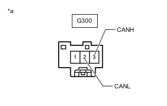
*a Rear view of wire harness connector
(to CAN Junction Terminal)
Disconnect the CAN junction terminal connector.
-
Measure the resistance according to the value(s) in the table below.
Standard Resistance Tester Connection Condition Specified Condition G300-3 (CANH) - G300-2 (CANL) Cable disconnected from negative (-) battery terminal 108 to 132 Ω Result Proceed to OK NG
OK
REPLACE CAN JUNCTION TERMINAL
NG
REPAIR OR REPLACE CAN BUS MAIN WIRE OR CONNECTOR
-
-
CHECK FOR SHORT IN CAN BUS WIRES (CAN JUNCTION CONNECTOR)
-
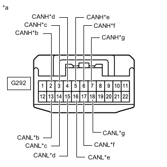
*a Front view of wire harness connector
(to CAN Junction Connector)
*b to Side Televition Camera Assembly RH *c to Parking Assist ECU *d to Rear Television Camera Aseembly *e to CAN Junction Terminal *f to Side Televition Camera Assembly LH *g to Front Television Camera Aseembly Disconnect the CAN junction connector.
-
Measure the resistance according to the value(s) in the table below.
Standard Resistance Tester Connection Condition Specified Condition Connected to G292-2 (CANH) - G292-13 (CANL) Cable disconnected from negative (-) battery terminal 200 Ω or higher Side televition camera assembly RH G292-3 (CANH) - G292-14 (CANL) Cable disconnected from negative (-) battery terminal 108 to 132 Ω Parking assist ECU G292-4 (CANH) - G292-15 (CANL) Cable disconnected from negative (-) battery terminal 200 Ω or higher Rear television camera aseembly G292-5 (CANH) - G292-16 (CANL) Cable disconnected from negative (-) battery terminal 108 to 132 Ω CAN Junction Terminal G292-6 (CANH) - G292-17 (CANL) Cable disconnected from negative (-) battery terminal 200 Ω or higher Side televition camera assembly LH G292-7 (CANH) - G292-18 (CANL) Cable disconnected from negative (-) battery terminal 200 Ω or higher Front television camera aseembly Result Result Proceed to OK A NG (Parking assist ECU CAN main wire) B NG (CAN junction terminal CAN main wire) C NG (Wire to sensor) D
A
REPLACE CAN JUNCTION CONNECTOR
C
CONNECT CONNECTOR Click here
D
GO TO STEP 25 Click here
B
-
-
CONNECT CONNECTOR
-
Reconnect the G292 CAN junction connector.
Result Proceed to NEXT
NEXT
-
-
CHECK FOR SHORT IN CAN BUS WIRES (PARKING ASSIST ECU - CAN JUNCTION CONNECTOR)
-
*a Front view of wire harness connector
(to Parking Assist ECU)
Disconnect the parking assist ECU connector.
-
Measure the resistance according to the value(s) in the table below.
Standard Resistance Tester Connection Condition Specified Condition I7-21 (CANH) - I7-20 (CANL) Cable disconnected from negative (-) battery terminal 108 to 132 Ω Result Proceed to OK NG
OK
REPLACE PARKING ASSIST ECU for LHD: Click here
REPLACE PARKING ASSIST ECU for RHD: Click hereNG
REPAIR OR REPLACE CAN BUS MAIN WIRE OR CONNECTOR
-
-
CONNECT CONNECTOR
-
Reconnect the G292 CAN junction connector.
Result Proceed to NEXT
NEXT
-
-
CHECK FOR SHORT IN CAN BUS WIRES (CAN JUNCTION TERMINAL - CAN JUNCTION CONNECTOR)
-
*a Rear view of wire harness connector
(to CAN Junction Terminal)
Disconnect the No. 2 CAN junction terminal connector.
-
Measure the resistance according to the value(s) in the table below.
Standard Resistance Tester Connection Condition Specified Condition G300-3 (CANH) - G300-2 (CANL) Cable disconnected from negative (-) battery terminal 108 to 132 Ω Result Proceed to OK NG
OK
REPLACE CAN JUNCTION TERMINAL
NG
REPAIR OR REPLACE CAN BUS MAIN WIRE OR CONNECTOR
-
-
CHECK FOR SHORT IN CAN BUS WIRES (CAN JUNCTION CONNECTOR)
-

*a Front view of wire harness connector
(to CAN Junction Connector)
*b Front view of DLC3 *c to Side Televition Camera Assembly RH *d to Parking Assist ECU *e to Rear Television Camera Aseembly *f to CAN Junction Terminal *g to Side Televition Camera Assembly LH *h to Front Television Camera Aseembly Disconnect the CAN junction connector.
-
Measure the resistance according to the value(s) in the table below.
Standard Resistance Tester Connection Condition Specified Condition Connected to G292-2 (CANH) - G48-4 (CG) Cable disconnected from negative (-) battery terminal 200 Ω or higher Side televition camera assembly RH G292-13 (CANL) - G48-4 (CG) G292-2 (CANH) - G48-16 (BAT) Cable disconnected from negative (-) battery terminal 6 kΩ or higher G292-13 (CANL) - G48-16 (BAT) G292-3 (CANH) - G48-4 (CG) Cable disconnected from negative (-) battery terminal 200 Ω or higher Parking assist ECU G292-14 (CANL) - G48-4 (CG) G292-3 (CANH) - G48-16 (BAT) Cable disconnected from negative (-) battery terminal 6 kΩ or higher G292-14 (CANL) - G48-16 (BAT) G292-4 (CANH) - G48-4 (CG) Cable disconnected from negative (-) battery terminal 200 Ω or higher Rear television camera aseembly G292-15 (CANL) - G48-4 (CG) G292-4 (CANH) - G48-16 (BAT) Cable disconnected from negative (-) battery terminal 6 kΩ or higher G292-15 (CANL) - G48-16 (BAT) G292-5 (CANH) - G48-4 (CG) Cable disconnected from negative (-) battery terminal 200 Ω or higher CAN Junction Terminal G292-16 (CANL) - G48-4 (CG) G292-5 (CANH) - G48-16 (BAT) Cable disconnected from negative (-) battery terminal 6 kΩ or higher G292-16 (CANL) - G48-16 (BAT) G292-6 (CANH) - G48-4 (CG) Cable disconnected from negative (-) battery terminal 200 Ω or higher Side televition camera assembly LH G292-17 (CANL) - G48-4 (CG) G292-6 (CANH) - G48-16 (BAT) Cable disconnected from negative (-) battery terminal 6 kΩ or higher G292-17 (CANL) - G48-16 (BAT) G292-7 (CANH) - G48-4 (CG) Cable disconnected from negative (-) battery terminal 200 Ω or higher Front television camera aseembly G292-18 (CANL) - G48-4 (CG) G292-7 (CANH) - G48-16 (BAT) Cable disconnected from negative (-) battery terminal 6 kΩ or higher G292-18 (CANL) - G48-16 (BAT) Result Result Proceed to OK A NG (Parking assist ECU CAN main wire) B NG (CAN junction terminal CAN main wire) C NG (Wire to sensor) D
A
REPLACE CAN JUNCTION CONNECTOR
C
CONNECT CONNECTOR Click here
D
CHECK FOR SHORT IN CAN BUS WIRES (SENSOR) Click here
B
-
-
CONNECT CONNECTOR
-
Reconnect the G292 CAN junction connector.
Result Proceed to NEXT
NEXT
-
-
CHECK FOR SHORT IN CAN BUS WIRES (PARKING ASSIST ECU - CAN JUNCTION CONNECTOR)
-

*a Front view of wire harness connector
(to Parking Assist ECU)
Disconnect the parking assist ECU connector.
-
Measure the resistance according to the value(s) in the table below.
Standard Resistance Tester Connection Condition Specified Condition I7-21 (CANH) - G48-4 (CG) Cable disconnected from negative (-) battery terminal 200 Ω or higher I7-20 (CANL) - G48-4 (CG) I7-21 (CANH) - G48-16 (BAT) Cable disconnected from negative (-) battery terminal 6 kΩ or higher I7-20 (CANL) - G48-16 (BAT) Result Proceed to OK NG
OK
REPLACE PARKING ASSIST ECU for LHD: Click here
REPLACE PARKING ASSIST ECU for RHD: Click hereNG
REPAIR OR REPLACE CAN BUS MAIN WIRE OR CONNECTOR
-
-
CONNECT CONNECTOR
-
Reconnect the G292 CAN junction connector.
Result Proceed to NEXT
NEXT
-
-
CHECK FOR SHORT IN CAN BUS WIRES (CAN JUNCTION TERMINAL - CAN JUNCTION CONNECTOR)
-

*a Rear view of wire harness connector
(to CAN Junction Terminal)
*b Front view of DLC3 Disconnect the CAN junction terminal connector.
-
Measure the resistance according to the value(s) in the table below.
Standard Resistance Tester Connection Condition Specified Condition G300-3 (CANH) - G48-4 (CG) Cable disconnected from negative (-) battery terminal 200 Ω or higher G300-2 (CANL) - G48-4 (CG) G300-3 (CANH) - G48-16 (BAT) Cable disconnected from negative (-) battery terminal 6 kΩ or higher G300-2 (CANL) - G48-16 (BAT) Result Proceed to OK NG
OK
REPLACE CAN JUNCTION TERMINAL
NG
REPAIR OR REPLACE CAN BUS MAIN WIRE OR CONNECTOR
-
-
CHECK FOR SHORT IN CAN BUS WIRES (SENSOR)
-
Reconnect the wire harness connectors.
-
*a Rear view of wire harness connector
(to CAN Junction Terminal)
*b Front view of DLC3 Disconnect the connector that includes terminals CANH and CANL from the sensor to which the short circuited main/branch line is connected.
-
Measure the resistance according to the value(s) in the table below.
Standard Resistance Tester Connection Condition Specified Condition G300-3 (CANH) - G300-2 (CANL) Cable disconnected from negative (-) battery terminal 54 to 69 Ω G300-3 (CANH) - G48-4 (CG) Cable disconnected from negative (-) battery terminal 200 Ω or higher G300-2 (CANL) - G48-4 (CG) G300-3 (CANH) - G48-16 (BAT) Cable disconnected from negative (-) battery terminal 6 kΩ or higher G300-2 (CANL) - G48-16 (BAT) Tech Tips
-
If the resistance becomes normal (between 54 and 69 Ω) when the connector is disconnected from the ECU or sensor, there may be a short to CAN bus lines in the sensor.
-
If the resistance changes to 6 kΩ or higher when the connector is disconnected from the sensor, there may be a short to B+ in the sensor.
-
If the resistance changes to 200 Ω or higher when the connector is disconnected from the sensor, there may be a short to GND in the sensor.
-
If the resistance does not become normal when the connector is disconnected from the sensor, check for a short circuit in the wire harness and repair or replace the wire harness or connector if necessary.
Result Proceed to OK NG -
OK
REPLACE SENSOR
NG
REPAIR OR REPLACE HARNESS OR CONNECTOR
-