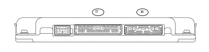
MULTI-TERRAIN MONITOR SYSTEM TERMINALS OF ECU
-
PARKING ASSIST ECU
-
Disconnect the I6 parking assist ECU connector.
-
Measure the voltage and resistance according to the value(s) in the table below.
Terminal No. (Symbol) Wiring Color Terminal Description Condition Specified Condition I6-1 (+B) - I6-4 (GND1) L - W-B Power source signal Always 11 to 14 V I6-4 (GND1) - Body ground W-B - Body ground Ground Always Below 1 Ω I6-8 (IG) - I6-4 (GND1) L - W-B IG power source signal Engine switch on (IG) 11 to 14 V I6-9 (ACC) - I6-4 (GND1) P - W-B ACC power source signal Engine switch on (ACC) 11 to 14 V -
Reconnect the I6 parking assist ECU connector.
-
Measure the voltage according to the value(s) in the table below.
Terminal No. (Symbol) Wiring Color Terminal Description Condition Specified Condition I6-5 (MPOS) - I6-4 (GND1) LG - W-B Panoramic view monitor switch (multi-terrain monitor switch) power source signal Engine switch on (IG), panoramic view monitor switch (multi-terrain monitor switch) on 5.5 to 6.5 V Engine switch on (IG), panoramic view monitor switch (multi-terrain monitor switch) off Below 1 V I6-10 (TX-) LG AVC-LAN communication signal - - I6-11 (TX+) L AVC-LAN communication signal - - I7-2 (DCB+) - I7-3 (DGND) B - GR Power source to side television camera LH Engine switch on (ACC) 5.5 to 7.05 V I7-3 (DGND) - Body ground GR - Body ground Side television camera LH ground (shield) Always Below 1 Ω I7-4 (DCV-) - I6-4 (GND1) W - W-B Side television camera LH ground Always Below 1 Ω I7-5 (DCV+) - I7-3 (DGND) R - GR Side television camera LH display signal input Engine switch on (IG), panoramic view monitor switch (multi-terrain monitor switch) on, camera lens not covered, displaying image Pulse generation (See waveform 1) Engine switch on (IG), panoramic view monitor switch (multi-terrain monitor switch) on, camera lens covered, blacking out screen Pulse generation (See waveform 2) I7-10 (SCV+) - I7-32 (SGND) R - GR Side television camera RH display signal input Waveform 1: Engine switch on (IG), panoramic view monitor switch (multi-terrain monitor switch) on, camera lens not covered, displaying image Pulse generation (See waveform 1) Waveform 2: Engine switch on (IG), panoramic view monitor switch (multi-terrain monitor switch) on, camera lens covered, blacking out screen Pulse generation (See waveform 2) I7-11 (BCB+) - I7-35 (BGND) B - GR Power source to front television camera Engine switch on (ACC) 5.5 to 7.05 V I7-12 (BCV+) - I7-35 (BGND) R - GR Front television camera display signal input Waveform 1: Engine switch on (IG), panoramic view monitor switch (multi-terrain monitor switch) on, camera lens not covered, displaying image Pulse generation (See waveform 1) Waveform 2: Engine switch on (IG), panoramic view monitor switch (multi-terrain monitor switch) on, camera lens covered, blacking out screen Pulse generation (See waveform 2) I7-14 (CB+) - I7-37 (CGND) B - G Power source to rear television camera Engine switch on (ACC) 5.5 to 7.05 V I7-15 (CV+) - I6-4 (GND1) R - W-B Rear television camera display signal input Engine switch on (IG), panoramic view monitor switch (multi-terrain monitor switch) on, camera lens not covered, displaying image Pulse generation (See waveform 1) Engine switch on (IG), panoramic view monitor switch (multi-terrain monitor switch) on, camera lens covered, blacking out screen Pulse generation (See waveform 2) I7-16 (NS+) - I6-4 (GND1) G - W-B Video signal Engine switch on (IG), panoramic view monitor switch (multi-terrain monitor switch) on, camera lens not covered, displaying image Pulse generation (See waveform 1) Engine switch on (IG), panoramic view monitor switch (multi-terrain monitor switch) on, camera lens covered, blacking out screen Pulse generation (See waveform 2) I7-17 (NS-) - I6-4 (GND1) L - W-B Video signal ground Always Below 1 Ω I7-18 (NSG) - Body ground GR - Body ground Shield ground Always Below 1 Ω I7-26 (ISSW) - Body ground W-B - Body ground Ground Always Below 1 Ω I7-27 (REV) - I6-4 (GND1) R - W-B Revers signal Engine switch on (IG), shift lever in R 11 to 14 V Engine switch on (IG), shift lever not in R Below 1 V I7-31 (SCB+) - I7-32 (SGND) B - GR Power source to side television camera RH Engine switch on (ACC) 5.5 to 7.05 V I7-32 (SGND) - Body ground GR - Body ground Side television camera RH ground (shield) Always Below 1 Ω I7-33 (SCV-) - I6-4 (GND1) W - W-B Side television camera RH ground Always Below 1 Ω I7-35 (BGND) - Body ground GR - Body ground Front television camera assembly ground (shield) Always Below 1 Ω I7-36 (BCV-) - I6-4 (GND1) W - W-B Front television camera ground Always Below 1 Ω I7-37 (CGND) - Body ground G - Body ground Rear television camera ground Always Below 1 Ω I7-38 (CV-) - I6-4 (GND1) W - W-B Rear television camera ground Always Below 1 Ω I7-39 (CANL) W CAN communication signal - - I7-40 (CANH) B CAN communication signal - - -
Using an oscilloscope, check waveform.
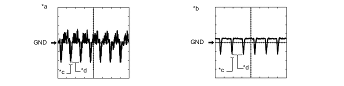
Text in Illustration *a Waveform A *b Waveform B *c Synchronization Signal *d Video Waveform
-
Waveform
Item Content Terminal No. (Symbol)
-
I7-15 (CV+) - I7-37 (CGND)
-
I7-10 (SCV+) - I7-32 (SGND)
-
I7-12 (BCV+) - I7-35 (BGND)
-
I7-5 (DCV+) - I7-3 (DGND)
-
I7-16 (NS+) - I7-17 (NS-)
Tool Setting 200 mV/DIV., 50 μsec./DIV. Condition
-
Waveform A: Engine switch on (IG), shift lever in R and camera lens is not covered, displaying an image.
-
Waveform B: Engine switch on (IG), shift lever in R and camera lens is covered, blacking out the screen.
Tech Tips
The video waveform changes according to the image sent by the rear television camera assembly.
-
-
-
-
NAVIGATION RECEIVER ASSEMBLY (for Navigation Receiver Type) Click here
-
RADIO AND DISPLAY RECEIVER ASSEMBLY (for Radio and Display Type) Click here