BLIND SPOT MONITOR SYSTEM Reverse Signal Circuit
DESCRIPTION
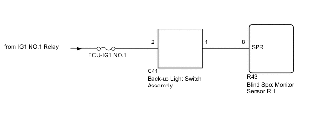
The blind spot monitor sensor RH receives a reverse signal from the back-up light switch assembly.
WIRING DIAGRAM
CAUTION / NOTICE / HINT
Note
Inspect the fuses for circuits related to this system before performing the following inspection procedure.
PROCEDURE
-
INSPECT BACK-UP LIGHT SWITCH ASSEMBLY
-
Remove the back-up light switch assembly Click here.
-
Inspect the back-up light switch assembly Click here.
NG 
REPLACE BACK-UP LIGHT SWITCH ASSEMBLY Click here
OK 
-
-
CHECK HARNESS AND CONNECTOR (BACK-UP LIGHT SWITCH ASSEMBLY - BATTERY)
-
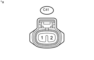
Text in Illustration *a Front view of wire harness connector
(to Back-up Light Switch Assembly)
Disconnect the back-up light switch assembly connector.
-
Measure the voltage according to the value(s) in the table below.
Standard Voltage Tester Connection Switch Condition Specified Condition C41-2 - Body ground Engine switch on (IG) 11 to 14 V Engine switch off Below 1 V
NG
REPAIR OR REPLACE HARNESS OR CONNECTOR
OK
-
-
CHECK HARNESS AND CONNECTOR (BLIND SPOT MONITOR SENSOR RH - BACK-UP LIGHT SWITCH ASSEMBLY)
-
Disconnect the R43 blind spot monitor sensor RH connector.
-
Disconnect the C41 back-up light switch assembly connector.
-
Measure the resistance according to the value(s) in the table below.
Standard Resistance Tester Connection Condition Specified Condition R43-8 (SPR) - C41-1 Always Below 1 Ω R43-8 (SPR) - Body ground Always 10 kΩ or higher
OK
PROCEED TO NEXT SUSPECTED AREA SHOWN IN PROBLEM SYMPTOMS TABLE Click here
NG
REPAIR OR REPLACE HARNESS OR CONNECTOR
-