PARKING ASSIST MONITOR SYSTEM(w/ Side Monitor System) ECU Power Source Circuit
DESCRIPTION
This circuit is the power source circuit to operate the parking assist ECU. The parking assist ECU controls the parking assist monitor system and side monitor system.
Tech Tips
-
The parking assist ECU is connected to other ECUs via CAN communication or AVC-LAN communication.
-
for Navigation Receiver Type:
If the parking assist ECU does not operate due to a power source problem, a navigation system DTC may be stored due to an AVC-LAN communication interruption.
-
for Radio and Display Type:
If the parking assist ECU does not operate due to a power source problem, an audio and visual system DTC may be stored due to an AVC-LAN communication interruption.
-
If the parking assist ECU does not operate due to a power source problem, other system DTCs may be stored due to a CAN communication interruption.
WIRING DIAGRAM
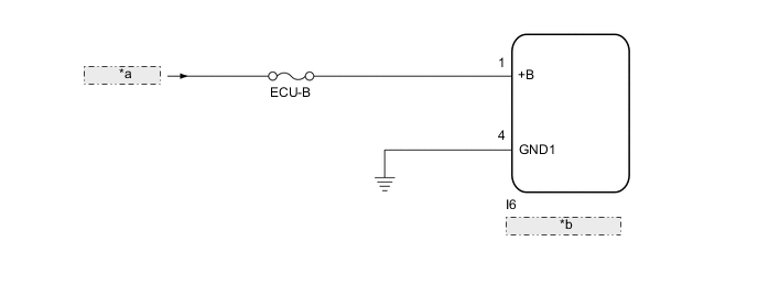
| *a | from Battery |
| *b | Parking Assist ECU |
CAUTION / NOTICE / HINT
Note
Inspect the fuse for circuits related to this system before performing the following inspection procedure.
PROCEDURE
-
CHECK FOR DTC (NAVIGATION SYSTEM OR AUDIO AND VISUAL SYSTEM)
-
Clear the DTCs.
-
for Navigation Receiver Type: Click here
-
for Radio and Display Type: Click here
-
-
Check for DTCs.
-
for Navigation Receiver Type: Click here
-
for Radio and Display Type: Click here
OK DTC B15D8 is not output. Tech Tips
The parking assist ECU is connected to the navigation receiver assembly*1 or radio and display receiver assembly*2 by AVC-LAN communication line. DTC B15D8 may be stored to the navigation receiver assembly*1 or radio and display receiver assembly*2 due to the power source condition or changes in the power supply waveform for the parking assist ECU, even though there is no problem with the AVC-LAN communication system.
-
*1: for Navigation Receiver Type
-
*2: for Radio and Display Type
Result Result Proceed to OK A NG (for Navigation Receiver Type) B NG (for Radio and Display Type) C -
B 
GO TO NAVIGATION SYSTEM Click here
C
GO TO AUDIO AND VISUAL SYSTEM Click here
A 
-
-
CHECK HARNESS AND CONNECTOR (PARKING ASSIST ECU - BATTERY AND BODY GROUND)
-
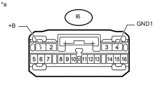
Text in Illustration *a Front view of wire harness connector
(to Parking Assist ECU)
Disconnect the I6 parking assist ECU connector.
-
Measure the resistance according to the value(s) in the table below.
Standard Resistance Tester Connection Condition Specified Condition I6-4 (GND1) - Body ground Always Below 1 Ω -
Measure the voltage according to the value(s) in the table below.
Standard Voltage Tester Connection Condition Specified Condition I6-1 (+B) - I6-4 (GND1) Always 10 to 16 V
OK
PROCEED TO NEXT SUSPECTED AREA SHOWN IN PROBLEM SYMPTOMS TABLE Click here
NG
REPAIR OR REPLACE HARNESS OR CONNECTOR
-