PARKING ASSIST MONITOR SYSTEM(w/ Side Monitor System) TERMINALS OF ECU
-
PARKING ASSIST ECU
-
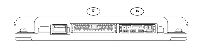
Disconnect the I6 and I7 parking assist ECU connectors.
-
Measure the voltage and resistance according to the value(s) in the table below.
Terminal No. (Symbol) Wiring Color Terminal Description Condition Specified Condition I6-1 (+B) - I6-4 (GND1) L - W-B Power source signal Always 10 to 16 V I6-4 (GND1) - Body ground W-B - Body ground Ground Always Below 1 Ω I6-8 (IG) - I6-4 (GND1) L - W-B IG power source signal Engine switch on (IG) 10 to 16 V Engine switch off Below 1 V I6-9 (ACC) - I6-4 (GND1) P - W-B ACC power source signal Engine switch on (ACC) 10 to 16 V Engine switch off Below 1 V I7-8 (BLSW) - I6-4 (GND1) L - W-B Front and side monitor main switch power source signal Engine switch on (IG), front and side monitor main switch on 10 to 16 V -
Reconnect the I6 and I7 parking assist ECU connectors.
-
Measure the voltage, resistance and waveform according to the value(s) in the table below.
Terminal No. (Symbol) Wiring Color Terminal Description Condition Specified Condition I6-10 (TX-) LG AVC-LAN communication signal - - I6-11 (TX+) L AVC-LAN communication signal - - I7-15 (CV+) - I7-37 (CGND) R - GR Rear television camera display signal input Engine switch on (IG), camera lens not covered, displaying image Pulse generation (See waveform 1) Engine switch on (IG), camera lens covered, blacking out screen Pulse generation (See waveform 2) I7-14 (CB+) - I7-37 (CGND) B - GR Power source to rear television camera Engine switch on (IG) 5.5 to 7.05 V I7-27 (REV) - I6-4 (GND1) R - W-B Reverse signal Engine switch on (IG), shift lever in R 7.5 to 14 V Engine switch on (IG), shift lever not in R Below 1 V I7-37 (CGND) - I6-4 (GND1) GR - W-B Rear television camera ground (shield) Always Below 1 Ω I7-38 (CV-) - I7-37 (CGND) W - GR Rear television camera ground Always Below 1 V -
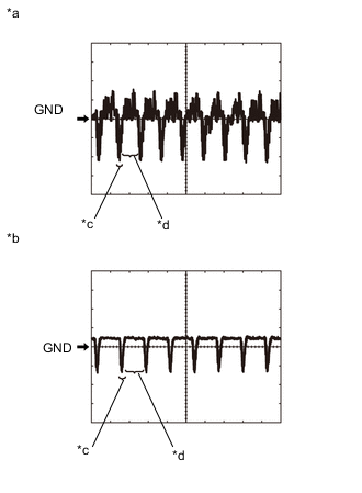
Text in Illustration *a Waveform 1 *b Waveform 2 *c Synchronized Signal *d Video Waveform Using an oscilloscope, check waveform.
Tech Tips
The video waveform changes according to the image sent by the rear television camera assembly.
-
Waveform 1
Measurement Condition Item Content Terminal No. (Symbol) I7-15 (CV+) - I7-37 (CGND) Tool Setting 200 mV/DIV., 50 μsec./DIV. Condition Engine switch on (IG), camera lens is not covered, displaying an image. -
Waveform 2
Measurement Condition Item Content Terminal No. (Symbol) I7-15 (CV+) - I7-37 (CGND) Tool Setting 200 mV/DIV., 50 μsec./DIV. Condition Engine switch on (IG), camera lens is covered, blacking out the screen.
-
-
-
NAVIGATION RECEIVER ASSEMBLY (for Navigation Receiver Type) Click here
-
RADIO AND DISPLAY RECEIVER ASSEMBLY (for Radio and Display Type) Click here
-
MAIN BODY ECU (MULTIPLEX NETWORK BODY ECU) Click here