PARKING ASSIST MONITOR SYSTEM(for Camera built-in ECU), Diagnostic DTC:C1621
| DTC Code | DTC Name |
|---|---|
| C1621 | Back Camera Power Supply Failure |
DESCRIPTION
This DTC is stored if the rear television camera assembly judges as a result of its self check that the signals or signal lines between the rear television camera assembly and navigation receiver assembly are not normal.
| DTC Code | DTC Detection Condition | Trouble Area |
|---|---|---|
| C1621 | Rear television camera assembly power supply failure |
|
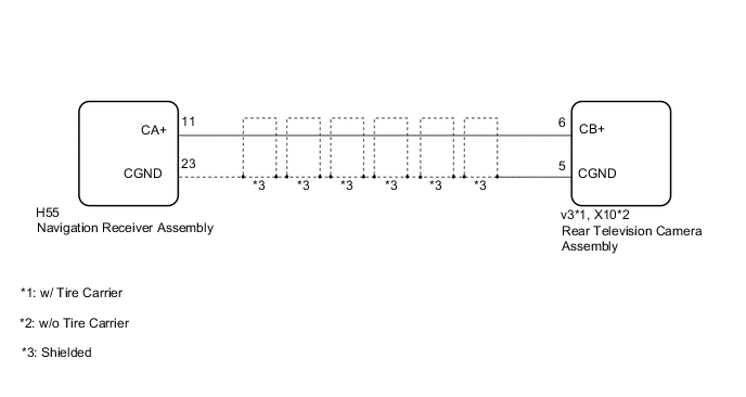
WIRING DIAGRAM
CAUTION / NOTICE / HINT
Note
-
If the cable was disconnected from and reconnected to the negative (-) battery terminal, the estimated course lines may not be displayed on the image of the area behind the vehicle. In this case, perform "Correct the Steering Angle Neutral Point" Click here.
-
Depending on the parts that are replaced or operations that are performed during vehicle inspection or maintenance, calibration of other systems as well as the parking assist monitor system may be needed Click here.
PROCEDURE
-
CHECK DTC OUTPUT
-
Clear the DTCs Click here.
-
Check for DTCs Click here.
Result Result Proceed to No DTC is output A DTC is output B
A 
USE SIMULATION METHOD TO CHECK Click here
B 
-
-
CHECK HARNESS AND CONNECTOR (NAVIGATION RECEIVER ASSEMBLY - REAR TELEVISION CAMERA ASSEMBLY)
-
Disconnect the H55 navigation receiver assembly connector.
-
Disconnect the v3*1 or X10*2 rear television camera assembly connector.
-
*1: w/ Tire Carrier
-
*2: w/o Tire Carrier
-
-
Measure the resistance according to the value(s) in the table below.
Standard Resistance w/ Tire Carrier Tester Connection Condition Specified Condition H55-11 (CA+) - v3-6 (CB+) Always Below 1 Ω H55-23 (CGND) - v3-5 (CGND) Always Below 1 Ω H55-11 (CA+) - H55-23 (CGND) Always 10 kΩ or higher H55-11 (CA+) or v3-6 (CB+) - Body ground Always 10 kΩ or higher H55-23 (CGND) or v3-5 (CGND) - Body ground Always Below 1 Ω w/o Tire Carrier Tester Connection Condition Specified Condition H55-11 (CA+) - X10-6 (CB+) Always Below 1 Ω H55-23 (CGND) - X10-5 (CGND) Always Below 1 Ω H55-11 (CA+) - H55-23 (CGND) Always 10 kΩ or higher H55-11 (CA+) or X10-6 (CB+) - Body ground Always 10 kΩ or higher H55-23 (CGND) or X10-5 (CGND) - Body ground Always Below 1 Ω
NG
REPAIR OR REPLACE HARNESS OR CONNECTOR
OK
-
-
CHECK NAVIGATION RECEIVER ASSEMBLY (CA+, CGND)
-
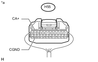
Text in Illustration *a Component with harness connected
(Navigation Receiver Assembly)
Remove the navigation receiver assembly with the connector still connected Click here.
-
Measure the voltage according to the value(s) in the table below.
Standard Voltage Tester Connection Switch Condition Specified Condition H55-11 (CA+) - H55-23 (CGND) Engine switch on (ACC) 5.5 to 7.05 V H55-11 (CA+) - H55-23 (CGND) Engine switch off Below 1 V Result Result Proceed to OK A NG (w/ Tire Carrier) B NG (w/o Tire Carrier) C
A
REPLACE NAVIGATION RECEIVER ASSEMBLY Click here
B
REPLACE REAR TELEVISION CAMERA ASSEMBLY Click here
C
REPLACE REAR TELEVISION CAMERA ASSEMBLY Click here
-