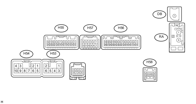
PARKING ASSIST MONITOR SYSTEM(for Camera built-in ECU) TERMINALS OF ECU
-
REAR TELEVISION CAMERA ASSEMBLY (w/ Tire Carrier)

-
Disconnect the v3 rear television camera assembly connector.
-
Measure the voltage and resistance according to the value(s) in the table below.
Terminal No. (Symbol) Wiring Color Terminal Description Condition Specified Condition v3-6 (CB+) - Body ground B - Body ground Power source Engine switch on (ACC) 5.5 to 7.05 V v3-5 (CGND) - Body ground BR - Body ground Shield ground Always Below 1 Ω -
Reconnect the v3 rear television camera assembly connector.
-
Measure the waveform according to the value(s) in the table below.
Terminal No. (Symbol) Wiring Color Terminal Description Condition Specified Condition v3-3 (CV+) - v3-2 (CV-) R - W Video signal Engine starts, shift lever in R, camera lens not covered, displaying image Pulse generation
(Refer to waveform 1)
Engine starts, shift lever in R, camera lens covered, blacking out screen Pulse generation
(Refer to waveform 2)
Tech Tips
A waterproof connector is used for the rear television camera assembly. Therefore, inspect the waveform at the navigation receiver assembly with the connector connected.
-

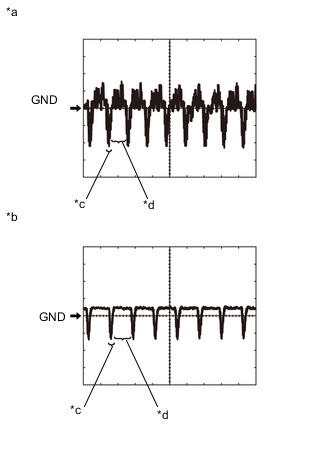
Text in Illustration *a Waveform 1 *b Waveform 2 *c Synchronized Signal *d Video Waveform Reference (Oscilloscope waveform):
Tech Tips
A waterproof connector is used for the rear television camera assembly. Therefore, inspect the waveform at the navigation receiver assembly with the connector connected.
-
Waveform
Measurement Condition Item Content Measurement terminal v3-3 (CV+) - v3-2 (CV-) Measurement setting 200 mV/DIV., 50 μsec./DIV. Condition Waveform 1: Engine starts, shift lever in R, camera lens is not covered, displaying an image
Waveform 2: Engine starts, shift lever in R, camera lens is covered, blacking out the screen
Tech Tips
-
The video waveform changes according to the image sent by the rear television camera assembly.
-
The video waveform is constantly output when the engine switch is on (ACC).
-
-
-
-
REAR TELEVISION CAMERA ASSEMBLY (w/o Tire Carrier)

-
Disconnect the X10 rear television camera assembly connector.
-
Measure the voltage and resistance according to the value(s) in the table below.
Terminal No. (Symbol) Wiring Color Terminal Description Condition Specified Condition X10-6 (CB+) - Body ground B - Body ground Power source Engine switch on (ACC) 5.5 to 7.05 V X10-5 (CGND) - Body ground BR - Body ground Shield ground Always Below 1 Ω -
Reconnect the X10 rear television camera assembly connector.
-
Measure the waveform according to the value(s) in the table below.
Terminal No. (Symbol) Wiring Color Terminal Description Condition Specified Condition X10-3 (CV+) - X10-2 (CV-) R - W Video signal Engine starts, shift lever in R, camera lens not covered, displaying image Pulse generation
(Refer to waveform 1)
Engine starts, shift lever in R, camera lens covered, blacking out screen Pulse generation
(Refer to waveform 2)
Tech Tips
A waterproof connector is used for the rear television camera assembly. Therefore, inspect the waveform at the navigation receiver assembly with the connector connected.
-

Text in Illustration *a Waveform 1 *b Waveform 2 *c Synchronized Signal *d Video Waveform Reference (Oscilloscope waveform):
Tech Tips
A waterproof connector is used for the rear television camera assembly. Therefore, inspect the waveform at the navigation receiver assembly with the connector connected.
-
Waveform 1
Measurement Condition Item Content Measurement terminal X10-3 (CV+) - X10-2 (CV-) Measurement setting 200 mV/DIV., 50 μsec./DIV. Condition Waveform 1: Engine starts, shift lever in R, camera lens is not covered, displaying an image
Waveform 2: Engine starts, shift lever in R, camera lens is covered, blacking out the screen
Tech Tips
-
The video waveform changes according to the image sent by the rear television camera assembly.
-
The video waveform is constantly output when the engine switch is on (ACC).
-
-
-
-
NAVIGATION RECEIVER ASSEMBLY
-
Measure the voltage, resistance and waveform according to the value(s) in the table below.
Terminal No. (Symbol) Wiring Color Terminal Description Condition Specified Condition H55-11 (CA+) - H55-23 (CGND) B - Shielded Rear television camera assembly power supply Engine switch on (ACC) 5.5 to 7.05 V H55-12 (V+) - H55-24 (V-) R - W Video signal Engine starts, shift lever in R, camera lens not covered, displaying image Pulse generation
(Refer to waveform 1)
Engine starts, shift lever in R, camera lens covered, blacking out screen Pulse generation
(Refer to waveform 2)
H55-24 (V-) - H55-23 (CGND) W - Shielded Ground Always Below 1 Ω H56-2 (REV) - H54-7 (GND1) R - BR Reverse signal See "Vehicle Signal Check Mode" in Operation Check Click here
- H56-17 (SPD) - H54-7 (GND1) R - BR Speed signal from combination meter assembly See "Vehicle Signal Check Mode" in Operation Check Click here
- Tech Tips
A waterproof connector is used for the rear television camera assembly. Therefore, inspect the waveform at the navigation receiver assembly with the connector connected.
-
Text in Illustration *a Waveform 1 *b Waveform 2 *c Synchronized Signal *d Video Waveform Reference (Oscilloscope waveform):
Tech Tips
A waterproof connector is used for the rear television camera assembly. Therefore, inspect the waveform at the navigation receiver assembly with the connector connected.
-
Waveform
Measurement Condition Item Content Measurement terminal H55-12 (V+) - H55-24 (V-) Measurement setting 200 mV/DIV., 50 μsec./DIV. Condition Waveform 1: Engine starts, shift lever in R, camera lens is not covered, displaying an image
Waveform 2: Engine starts, shift lever in R, camera lens is covered, blacking out the screen
Tech Tips
-
The video waveform changes according to the image sent by the rear television camera assembly.
-
The video waveform is constantly output when the engine switch is on (ACC).
-
-
-