TOYOTA PARKING ASSIST-SENSOR SYSTEM(w/o Multi-display) Clearance Sonar Main Switch Circuit
DESCRIPTION
When the back sonar or clearance sonar switch assembly is turned on, the on signal is input into the ECU.
WIRING DIAGRAM
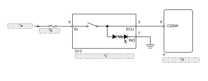
| *a | from Ignition Switch |
| *b | ECU-IG NO. 2 |
| *c | Back Sonar or Clearance Sonar Switch Assembly |
| *d | Clearance Warning ECU |
CAUTION / NOTICE / HINT
Note
Inspect the fuses for circuits related to this system before performing the following inspection procedure.
PROCEDURE
-
INSPECT BACK SONAR OR CLEARANCE SONAR SWITCH ASSEMBLY
-
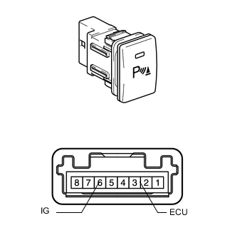
Remove the back sonar or clearance sonar switch assembly Click here.
-
Measure the resistance according to the value(s) in the table below.
Standard Resistance Tester Connection Switch Condition Specified Condition 3 (ECU) - 6 (IG) Pressed (on) Below 1 Ω 3 (ECU) - 6 (IG) Not pressed (off) 10 kΩ or higher
NG 
REPLACE BACK SONAR OR CLEARANCE SONAR SWITCH ASSEMBLY Click here
OK 
-
-
CHECK HARNESS AND CONNECTOR (BACK SONAR OR CLEARANCE SONAR SWITCH - BATTERY AND BODY GROUND)
-
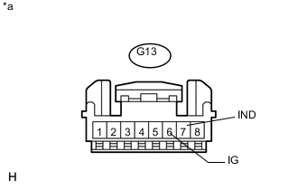
Text in Illustration *a Front view of wire harness connector
(to Back Sonar or Clearance Sonar Switch)
Disconnect the G13 back sonar or clearance sonar switch assembly connector.
-
Measure the voltage according to the value(s) in the table below.
Standard Voltage Tester Connection Switch Condition Specified Condition G13-6 (IG) - Body ground Ignition switch ON 11 to 14 V G13-6 (IG) - Body ground Ignition switch off Below 1 V -
Measure the resistance according to the value(s) in the table below.
Standard Resistance Tester Connection Condition Specified Condition G13-7 (IND) - Body ground Always Below 1 Ω
NG
REPAIR OR REPLACE HARNESS OR CONNECTOR
OK
-
-
CHECK HARNESS AND CONNECTOR (BACK SONAR OR CLEARANCE SONAR SWITCH - CLEARANCE WARNING ECU)
-
Disconnect the G13 back sonar or clearance sonar switch assembly connector.
-
Disconnect the I1 clearance warning ECU connector.
-
Measure the resistance according to the value(s) in the table below.
Standard Resistance Tester Connection Condition Specified Condition G13-3 (ECU) - I1-8 (CSSW) Always Below 1 Ω G13-3 (ECU) - Body ground Always 10 kΩ or higher
OK
PROCEED TO NEXT SUSPECTED AREA SHOWN IN PROBLEM SYMPTOMS TABLE Click here
NG
REPAIR OR REPLACE HARNESS OR CONNECTOR
-