PARKING ASSIST MONITOR SYSTEM(for Camera built-in ECU) Image from Camera for Parking Assist Monitor is Abnormal
DESCRIPTION
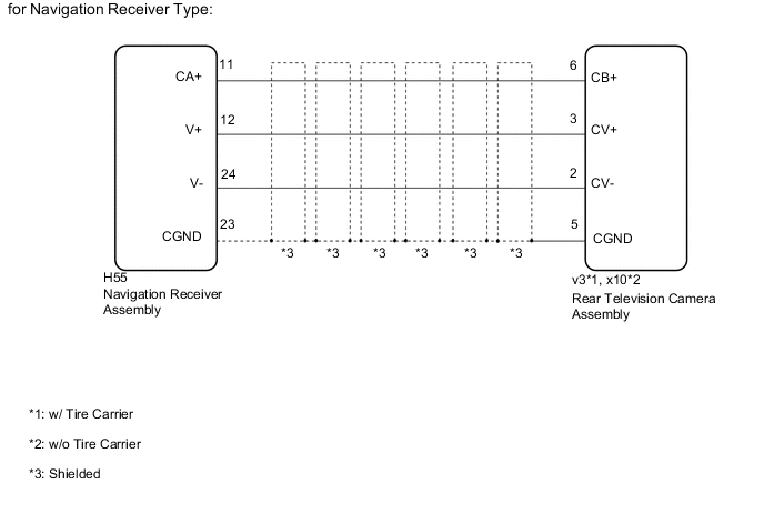
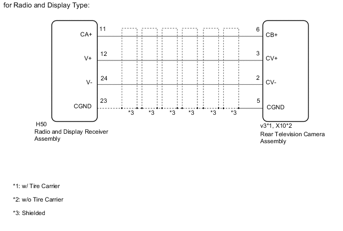
The video signal from the rear television camera assembly is transmitted to the navigation receiver assembly*1 or radio and display receiver assembly*2.
-
*1: for Navigation Receiver Type
-
*2: for Radio and Display Type
WIRING DIAGRAM
CAUTION / NOTICE / HINT
Note
-
If the cable was disconnected from and reconnected to the negative (-) battery terminal, the estimated course lines may not be displayed on the image of the area behind the vehicle. In this case, perform "Correct the Steering Angle Neutral Point" Click here.
-
Depending on the parts that are replaced or operations that are performed during vehicle inspection or maintenance, calibration of other systems as well as the parking assist monitor system may be needed Click here.
Tech Tips
Images may be unclear even in normal conditions if:
-
Electrical devices are used in the cabin (noise may occur in the image).
-
Accessories that generate radio waves have been installed (noise may occur in the image).
-
The outer mirror switch assembly is operated (noise may occur in the image).
-
The navigation receiver assembly*1 or radio and display receiver assembly*2 is cold (the image immediately after turning the engine switch on (IG) may be blurred or darker than normal).
-
*1: for Navigation Receiver Type
-
*2: for Radio and Display Type
-
The camera lens is dirty with snow, mud, etc.
-
A strong beam of light, such as a sunbeam or headlight, hits the camera.
-
It is too dark around the camera (at night etc.).
-
The ambient temperature around the camera is either too high or too low.
-
The vehicle is tilted at a steep angle.
-
The rear television camera assembly lens is scratched.
-
The rear television camera assembly lens has drops of water on it or the humidity is high.
-
When the camera is used under fluorescent lights, sodium lights, or mercury lights etc., the lights and the illuminated area may appear to flicker.
PROCEDURE
-
CHECK VEHICLE TYPE
-
Check the vehicle type.
Result Result Proceed to for Navigation Receiver Type A for Radio and Display Type B
B 
CHECK HARNESS AND CONNECTOR (REAR TELEVISION CAMERA ASSEMBLY - RADIO AND DISPLAY RECEIVER ASSEMBLY) Click here
A 
-
-
CHECK HARNESS AND CONNECTOR (REAR TELEVISION CAMERA ASSEMBLY - NAVIGATION RECEIVER ASSEMBLY)
-
Disconnect the v3*1 or X10*2 rear television camera assembly connector.
-
*1: w/ Tire Carrier
-
*2: w/o Tire Carrier
-
-
Disconnect the H55 navigation receiver assembly connector.
-
Measure the resistance according to the value(s) in the table below.
Standard Resistance w/ Tire Carrier Tester Connection Condition Specified Condition v3-6 (CB+) - H55-11 (CA+) Always Below 1 Ω v3-3 (CV+) - H55-12 (V+) Always Below 1 Ω v3-2 (CV-) - H55-24 (V-) Always Below 1 Ω v3-5 (CGND) - H55-23 (CGND) Always Below 1 Ω v3-6 (CB+) or H55-11 (CA+) - Body ground Always 10 kΩ or higher v3-3 (CV+) or H55-12 (V+) - Body ground Always 10 kΩ or higher v3-2 (CV-) or H55-24 (V-) - Body ground Always 10 kΩ or higher v3-5 (CGND) or H55-23 (CGND) - Body ground Always Below 1 Ω w/o Tire Carrier Tester Connection Condition Specified Condition X10-6 (CB+) - H55-11 (CA+) Always Below 1 Ω X10-3 (CV+) - H55-12 (V+) Always Below 1 Ω X10-2 (CV-) - H55-24 (V-) Always Below 1 Ω X10-5 (CGND) - H55-23 (CGND) Always Below 1 Ω X10-6 (CB+) or H55-11 (CA+) - Body ground Always 10 kΩ or higher X10-3 (CV+) or H55-12 (V+) - Body ground Always 10 kΩ or higher X10-2 (CV-) or H55-24 (V-) - Body ground Always 10 kΩ or higher X10-5 (CGND) or H55-23 (CGND) - Body ground Always Below 1 Ω
NG 
REPAIR OR REPLACE HARNESS OR CONNECTOR
OK
-
-
CHECK REAR TELEVISION CAMERA ASSEMBLY
-
Replace the rear television camera assembly with a new or known good one.
-
w/ Tire Carrier: Click here
-
w/o Tire Carrier: Click here
-
-
Check that the parking assist monitor system operates normally.
OK Parking assist monitor system operates normally.
OK
END (REAR TELEVISION CAMERA ASSEMBLY IS DEFECTIVE)
NG
REPLACE NAVIGATION RECEIVER ASSEMBLY Click here
-
-
CHECK HARNESS AND CONNECTOR (REAR TELEVISION CAMERA ASSEMBLY - RADIO AND DISPLAY RECEIVER ASSEMBLY)
-
Disconnect the v3*1 or X10*2 rear television camera assembly connector.
-
*1: w/ Tire Carrier
-
*2: w/o Tire Carrier
-
-
Disconnect the H50 radio and display receiver assembly connector.
-
Measure the resistance according to the value(s) in the table below.
Standard Resistance w/ Tire Carrier Tester Connection Condition Specified Condition v3-6 (CB+) - H50-11 (CA+) Always Below 1 Ω v3-3 (CV+) - H50-12 (V+) Always Below 1 Ω v3-2 (CV-) - H50-24 (V-) Always Below 1 Ω v3-5 (CGND) - H50-23 (CGND) Always Below 1 Ω v3-6 (CB+) or H50-11 (CA+) - Body ground Always 10 kΩ or higher v3-3 (CV+) or H50-12 (V+) - Body ground Always 10 kΩ or higher v3-2 (CV-) or H50-24 (V-) - Body ground Always 10 kΩ or higher v3-5 (CGND) or H50-23 (CGND) - Body ground Always Below 1 Ω w/o Tire Carrier Tester Connection Condition Specified Condition X10-6 (CB+) - H50-11 (CA+) Always Below 1 Ω X10-3 (CV+) - H50-12 (V+) Always Below 1 Ω X10-2 (CV-) - H50-24 (V-) Always Below 1 Ω X10-5 (CGND) - H50-23 (CGND) Always Below 1 Ω X10-6 (CB+) or H50-11 (CA+) - Body ground Always 10 kΩ or higher X10-3 (CV+) or H50-12 (V+) - Body ground Always 10 kΩ or higher X10-2 (CV-) or H50-24 (V-) - Body ground Always 10 kΩ or higher X10-5 (CGND) or H50-23 (CGND) - Body ground Always Below 1 Ω
NG
REPAIR OR REPLACE HARNESS OR CONNECTOR
OK
-
-
CHECK REAR TELEVISION CAMERA ASSEMBLY
-
Replace the rear television camera assembly with a new or known good one.
-
w/ Tire Carrier: Click here
-
w/o Tire Carrier: Click here
-
-
Check that the parking assist monitor system operates normally.
OK Parking assist monitor system operates normally.
OK
END (REAR TELEVISION CAMERA ASSEMBLY IS DEFECTIVE)
NG
REPLACE RADIO AND DISPLAY RECEIVER ASSEMBLY Click here
-