TOYOTA PARKING ASSIST-SENSOR SYSTEM(w/ Multi-display) Main Switch Circuit
DESCRIPTION
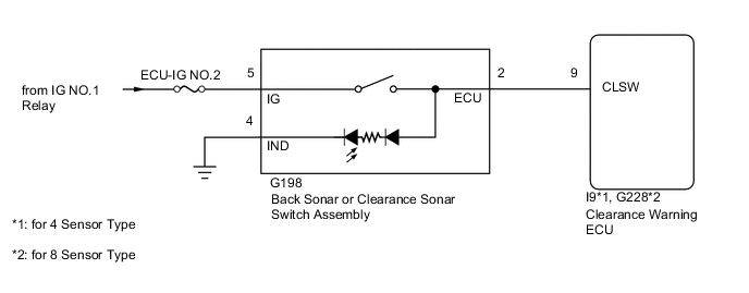
When the back sonar or clearance sonar switch assembly is turned on, the ON signal is input into the ECU.
WIRING DIAGRAM
CAUTION / NOTICE / HINT
Note
Inspect the fuses for circuits related to this system before performing the following procedure.
PROCEDURE
-
READ VALUE USING GTS
-
Connect the GTS to the DLC3.
-
Turn the Ignition switch ON.
-
Turn the GTS on.
-
Enter the following menus: Body / Clearance Sonar / Data List.
-
According to the display on the GTS, read the Data List.
Clearance Sonar Tester Display Measurement Item/Range Normal Condition Diagnostic Note Main Switch Back sonar or clearance sonar switch assembly / OFF or ON OFF: Back sonar or clearance sonar switch assembly off
ON: Back sonar or clearance sonar switch assembly on
- OK The display changes as shown above when the TOYOTA parking assist-sensor system is operated.
OK 
PROCEED TO NEXT SUSPECTED AREA SHOWN IN PROBLEM SYMPTOMS TABLE Click here
NG 
-
-
INSPECT BACK SONAR OR CLEARANCE SONAR SWITCH ASSEMBLY
-
Remove the back sonar or clearance sonar switch assembly Click here.
-
Inspect the back sonar or clearance sonar switch assembly Click here.
NG
REPLACE BACK SONAR OR CLEARANCE SONAR SWITCH ASSEMBLY Click here
OK
-
-
CHECK HARNESS AND CONNECTOR (BACK SONAR OR CLEARANCE SONAR SWITCH ASSEMBLY - CLEARANCE WARNING ECU, BATTERY AND BODY GROUND)
-
Disconnect the G198 back sonar or clearance sonar switch assembly connector.
-
Disconnect the I9*1 or G228*2 clearance warning ECU connector.
-
*1: for 4 Sensor Type
-
*2: for 8 Sensor Type
-
-
Measure the voltage according to the value(s) in the table below.
Standard Voltage Tester Connection Switch Condition Specified Condition G198-5 (IG) - Body ground Ignition switch ON 11 to 14 V -
Measure the resistance according to the value(s) in the table below.
Standard Resistance for 4 Sensor Type Tester Connection Condition Specified Condition G198-2 (ECU) - I9-9 (CLSW) Always Below 1 Ω G198-4 (IND) - Body ground Always Below 1 Ω G198-2 (ECU) - Body ground Always 10 kΩ or higher Standard Resistance for 8 Sensor Type Tester Connection Condition Specified Condition G198-2 (ECU) - G228-9 (CLSW) Always Below 1 Ω G198-4 (IND) - Body ground Always Below 1 Ω G198-2 (ECU) - Body ground Always 10 kΩ or higher Result Result Proceed to OK (for LHD) A OK (for RHD) B NG C
A
REPLACE CLEARANCE WARNING ECU Click here
B
REPLACE CLEARANCE WARNING ECU Click here
C
REPAIR OR REPLACE HARNESS OR CONNECTOR
-