TOYOTA PARKING ASSIST-SENSOR SYSTEM(w/ Multi-display) TERMINALS OF ECU
-
CHECK CLEARANCE WARNING ECU

Text in Illustration *A for 4 Sensor Type *B for 8 Sensor Type
-
Measure the voltage and resistance and check for pulse signals according to the value(s) in the table below.
for 4 Sensor Type Terminal No. (Symbol) Wiring Color Terminal Description Condition Specified Condition I9-22 (BOR) - I9-30 (E) P - W-B Power source for rear sensor circuit Ignition switch off Below 1.5 V Ignition switch ON, back sonar or clearance sonar switch on 7.2 to 8.8 V I9-14 (BBZ) - I9-13 (ER) GR - LG No. 1 clearance warning buzzer signal Buzzer not sounding Below 1 V When sonar detects obstacle (Buzzer sounds) Pulse generation
(See waveform 1)
I9-9 (CLSW) - I9-30 (E) V - W-B Clearance sonar main switch signal Ignition switch ON, back sonar or clearance sonar switch on 11 to 14 V Ignition switch ON, back sonar or clearance sonar switch off Below 1 V I9-1 (IG) - I9-30 (E) L - W-B IG power source signal Ignition switch off Below 1.5 V Ignition switch ON 11 to 14 V I9-30 (E) - Body ground W-B - Body ground Ground Always Below 1 Ω I9-23 (E1) - I9-30 (E) R - W-B Ground for rear sensors Always Below 1 Ω I9-24 (SOR) - I9-30 (E) W - W-B Rear sensor communication signal Ignition switch ON, back sonar or clearance sonar switch on, shift lever in R Pulse generation
(See waveform 2)
for 8 Sensor Type Terminal No. (Symbol) Wiring Color Terminal Description Condition Specified Condition G228-22 (BOR) - G228-30 (E) P - W-B Power source for rear sensor circuit Ignition switch off Below 1.5 V Ignition switch ON, back sonar or clearance sonar switch on 7.2 to 8.8 V G228-8 (SOF) - G228-30 (E) R - W-B Front sensor communication signal Ignition switch ON, back sonar or clearance sonar switch on, shift lever in R Pulse generation
(See waveform 2)
G228-14 (CBZ) - G228-30 (E) GR - W-B Clearance warning buzzer signal Ignition switch off Below 1.5 V Ignition switch ON, back sonar or clearance sonar switch on 11 to 14 V G228-13 (EF) - G228-30 (E) LG - W-B Ground for clearance warning buzzer When sonar detects obstacle (Buzzer sounds) Pulse generation
(See waveform 1)
G228-9 (CLSW) - G228-30 (E) V - W-B Clearance sonar main switch signal Ignition switch ON, back sonar or clearance sonar switch on 11 to 14 V Ignition switch ON, back sonar or clearance sonar switch off Below 1 V G228-1 (IG) - G228-30 (E) L - W-B IG power source signal Ignition switch off Below 1.5 V Ignition switch ON 11 to 14 V G228-30 (E) - Body ground W-B - Body ground Ground Always Below 1 Ω G228-23 (E1) - G228-30 (E) R - W-B Ground for rear sensors Always Below 1 Ω G228-6 (E5) - G228-30 (E) G - W-B Ground for front sensors Always Below 1 Ω G228-4 (BOF) - G228-30 (E) V - W-B Power source for front sensor circuit Ignition switch off Below 1.5 V Ignition switch ON, back sonar or clearance sonar switch on 7.2 to 8.8 V G228-24 (SOR) - G228-30 (E) W - W-B Rear sensor communication signal Ignition switch ON, back sonar or clearance sonar switch on, shift lever in R Pulse generation
(See waveform 2)
-
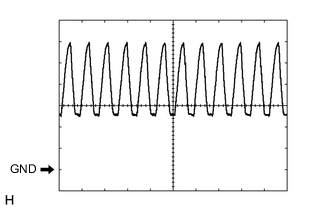
Using an oscilloscope, check waveform 1.
Measurement Condition Item Content Terminal No. (Symbol)
-
I9-14 (BBZ) - I9-13 (ER)*1
-
G228-13 (EF) -G228-30 (E)*2
Tool Setting 2 V/DIV., 500 μsec./DIV. Condition When sonar detects obstacle (Buzzer sounds)
-
*1: for 4 Sensor Type
-
*2: for 8 Sensor Type
-
-
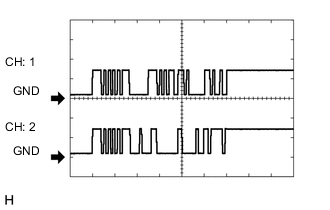
Using an oscilloscope, check waveform 2.
Measurement Condition Item Content Terminal No. (Symbol)
-
CH1: G228-8 (SOF) - G228-30 (E)*2
-
CH2: I9-24 (SOR) - I9-30 (E)*1
-
CH2: G228-24 (SOR) - G228-30 (E)*2
Tool Setting 5 V/DIV., 1 msec./DIV. Condition Ignition switch ON, back sonar or clearance sonar switch on, shift lever in R
-
*1: for 4 Sensor Type
-
*2: for 8 Sensor Type
-
-