TOYOTA PARKING ASSIST-SENSOR SYSTEM(w/ Multi-display) OPERATION CHECK
-
SELF-CHECK FUNCTION INSPECTION (INITIAL CHECK)
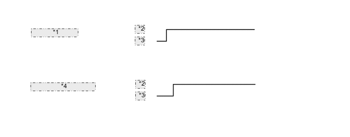
*1 Ignition Switch: *2 On *3 Off *4 Main Switch Operation:
-
Turn the ignition switch to ON.
-
Turn the back sonar or clearance sonar switch on.
-
Turn the ignition switch off.
-
Turn the ignition switch to ON.
-
Turn the back sonar or clearance sonar switch on and check that the following occurs:
1) The system starts detection operation mode.
Tech Tips
-
During the initial check, malfunction detection operates and obstacle detection does not operate.
-
In the detection operation mode, obstacle detection and malfunction detection operate.
-
If a sensor has an open circuit or a sensor malfunctions because it is wet or frozen, a malfunction display is shown in the multi-information display and the buzzer sounds.
-
If the ignition switch is turned to ON while the back sonar or clearance sonar switch on, the buzzer does not sound even though the malfunction detection operates.
-
-
-
MALFUNCTION DISPLAY (MULTI-INFORMATION DISPLAY)
-
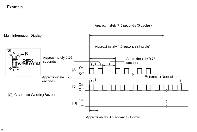
Open circuit indication
-
If there is an open circuit between the ultrasonic sensor and the clearance warning ECU, or a sensor is malfunctioning, the malfunction is displayed as shown in the illustration.
Tech Tips
-
If a sensor has an open circuit, check for DTCs and troubleshoot according to each inspection procedure Click here.
-
-
-
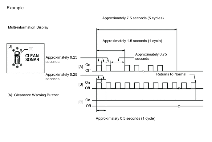
Frozen indication
-
If a sensor is covered with foreign matter, such as mud or snow, the affected sensor is displayed as shown in the illustration.
Tech Tips
If a sensor has an open circuit, check for DTCs and troubleshoot according toeach inspection procedure Click here.
-
-
-
DETECTION RANGE MEASUREMENT AND DISPLAY INSPECTION
-
Detection range measurement:
Note
Make sure that the vehicle does not move by applying the parking brake firmly.
-
Turn the ignition switch to ON.
-
Move the shift lever to R to check the ultrasonic sensors.
-
-
Turn the back sonar or clearance sonar switch on.
-
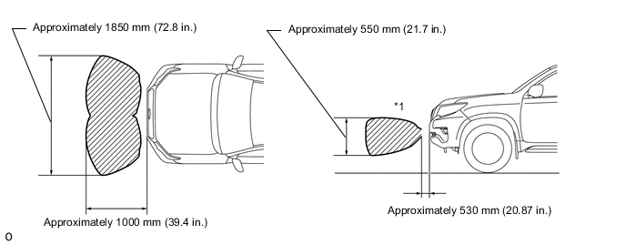
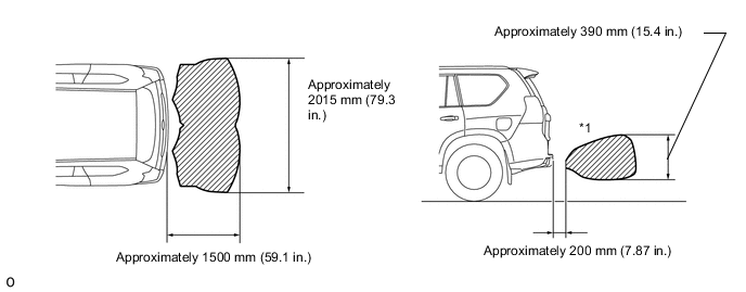
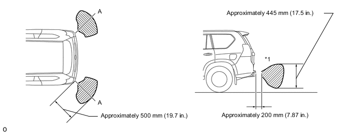
Move a φ 60 mm (2.36 in.) pole near each sensor to measure its detection range.
Note
-
These detection ranges are applicable when positioning a pole with a diameter of 60 mm (2.36 in.) parallel or perpendicular to the ground.
-
The ranges vary depending on the measuring method and type of obstacle (such as walls).
-
For close-range and medium-range detection, the values shown are for when using a pole with a diameter of 60 mm (2.36 in.). For long-range detection, the values shown are for when using walls.
-
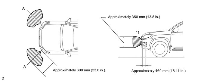
The No. 1 ultrasonic sensor side view detection range hatched area*1 represents the cross section of the top view of the detection range along the lines labeled A. The hatched area*1 does not represent the entire side view detection range.
-
Detection range of front corner sensors (for 8 Sensor Type)
-
Detection range of front center sensors (for 8 Sensor Type)
-
Detection range of rear center sensors
-
Detection range of rear corner sensors
-
-
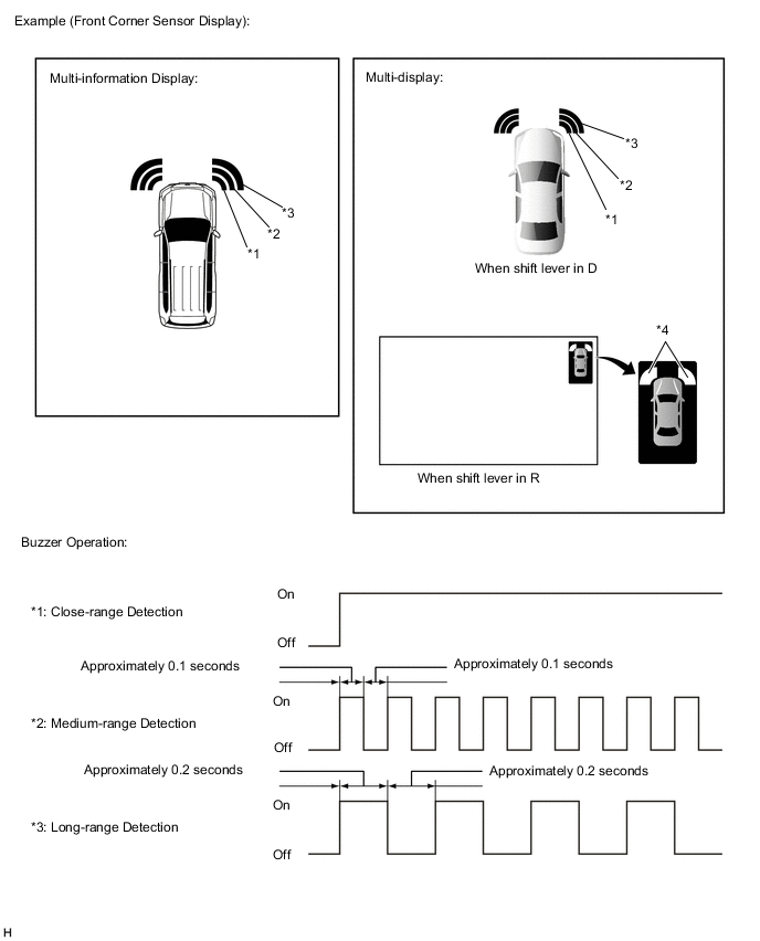
Check the displays and buzzer sounds when the ultrasonic sensors detect an obstacle.
-
Front corner sensors (for 8 Sensor Type)
Operation Condition Ignition Switch Back Sonar or Clearance Sonar Switch Shift Lever Position* Vehicle Speed ON ON In any position except P
-
Less than approximately 15 km/h (9.3 mph) if speed is increasing
-
Less than approximately 10 km/h (6.2 mph) if speed is decreasing
*: for Automatic Transmission
Tech Tips
Ultrasonic waves are used to measure the detection range; however, the detection range may vary depending on the ambient temperature.
-
-
Front center sensors (for 8 Sensor Type)
Operation Condition Ignition Switch Back Sonar or Clearance Sonar Switch Shift Lever Position Vehicle Speed ON ON except P*, R
-
Less than approximately 15 km/h (9.3 mph) if speed is increasing
-
Less than approximately 10 km/h (6.2 mph) if speed is decreasing
*: for Automatic Transmission
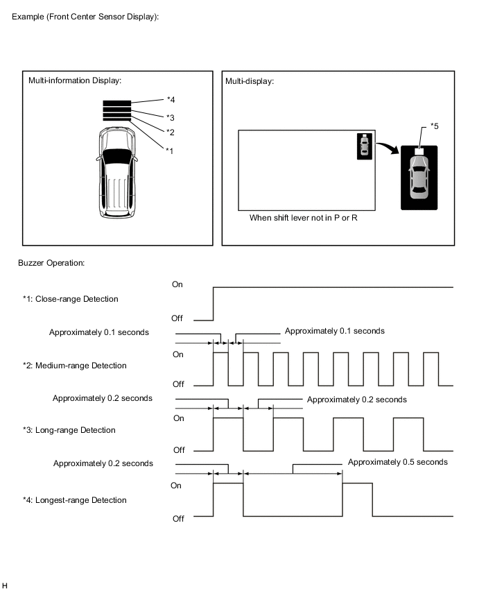
Tech Tips
Ultrasonic waves are used to measure the detection range; however, the detection range may vary depending on the ambient temperature.
-
-
Rear corner sensors
Operation Condition Ignition Switch Back Sonar or Clearance Sonar Switch Shift Lever Position Vehicle Speed ON ON R - 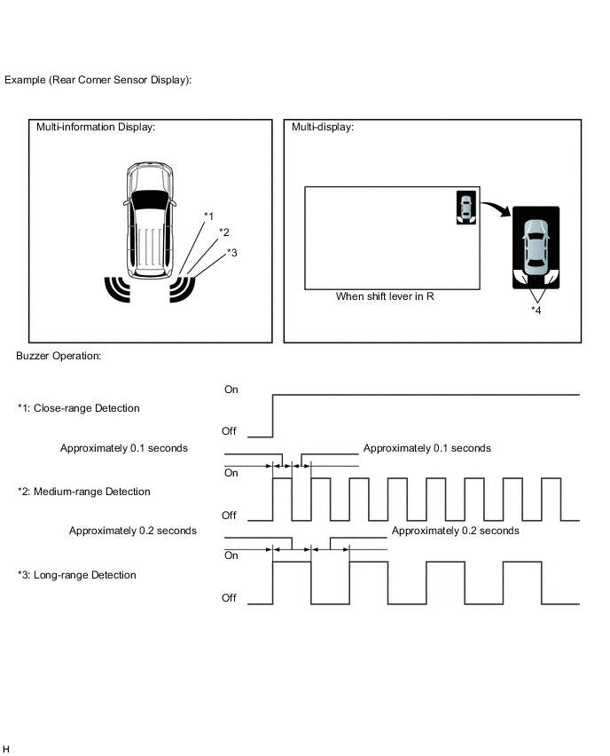
-
*4: When shift lever in R
Tech Tips
Ultrasonic waves are used to measure the detection range; however, the detection range may vary depending on the ambient temperature.
-
-
Rear center sensors
Operation Condition Ignition Switch Back Sonar or Clearance Sonar Switch Shift Lever Position Vehicle Speed ON ON R - 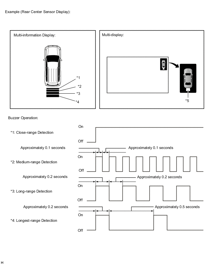
-
*5: When shift lever in R
Tech Tips
Ultrasonic waves are used to measure the detection range; however, the detection range may vary depending on the ambient temperature.
-
-
-