TOYOTA PARKING ASSIST-SENSOR SYSTEM(w/o Multi-display) TERMINALS OF ECU
-
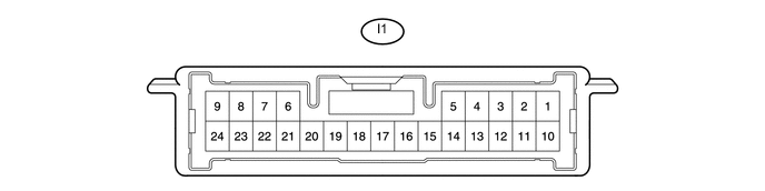
CHECK CLEARANCE WARNING ECU
-
Measure the voltage and resistance and check for pulse signals according to the value(s) in the table below.
Terminal No. (Symbol) Wiring Color Terminal Description Condition Specified Condition I1-3 (SPD) - I1-21 (E) R - W-B Vehicle speed signal Ignition switch ON, back sonar or clearance sonar switch on Alternating between 1.5 to 4.5 V I1-6 (SOR) - I1-22 (E2) W - R Rear ultrasonic sensor communication signal (Rear clearance sonar sensor) Ignition switch ON, back sonar or clearance sonar switch on, shift lever in R Pulse generation
(See waveform 2)
I1-8 (CSSW) - I1-21 (E) V - W-B Clearance sonar on/off switch signal Back sonar or clearance sonar switch on 11 to 14 V I1-10 (IG) - I1-21 (E) L - W-B IG signal/IG power source signal Ignition switch off Below 1 V Ignition switch ON 11 to 14 V I1-13 (RL) - I1-21 (E) R - W-B Reverse signal Ignition switch ON, shift lever in R 11 to 14 V Ignition switch ON, shift lever not in R Below 1 V I1-14 (BBZ) - I1-12 (EF) GR - LG No. 1 clearance warning buzzer signal Buzzer not sounding Below 1 V When sonar detects obstacle (buzzer sounds) Pulse generation
(See waveform 1)
I1-15 (L1) - I1-21 (E) LG - W-B Clearance warning ECU signal Clearance warning indicator LED for rear right sensor illuminates Below 3 V I1-17 (L3) - I1-21 (E) L - W-B Ultrasonic sensor (rear center right and left sensor) Clearance warning indicator LED for rear left sensor illuminates Below 3 V I1-19 (L5) - I1-21 (E) P - W-B Ultrasonic sensor (rear left sensor) Clearance warning indicator LED for back sensor illuminates Below 3 V I1-20 (L6) - I1-21 (E) R - W-B Ultrasonic sensor (rear right sensor) Clearance warning indicator's operation indicator illuminates Below 3 V I1-21 (E) - Body ground W-B - Body ground ECU ground Always Below 1 Ω I1-22 (E2) - I1-21 (E) R - W-B ECU ground Always Below 1 Ω I1-24 (BOR) - I1-22 (E2) P - R Rear ultrasonic sensor circuit power source Ignition switch off Below 1.5 V Ignition switch ON, back sonar or clearance sonar switch on 7.2 to 8.8 V -
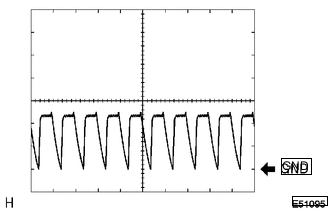
Using an oscilloscope, check waveform 1.
Measurement Condition Item Content Terminal No. (Symbol) I1-14 (BBZ) - I1-12 (EF) Tool Setting 2 V/DIV., 500 μsec./DIV. Condition When sonar detects obstacle (buzzer sounds) -
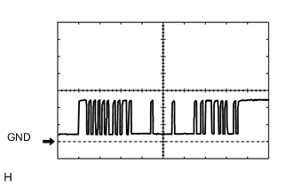
Using an oscilloscope, check waveform 2.
Measurement Condition Item Content Terminal No. (Symbol) I1-6 (SOR) - I1-22 (E2) Tool Setting 5 V/DIV., 1 msec./DIV. Condition Ignition switch ON, back sonar or clearance sonar switch on, shift lever in R
-