TELEMATICS SYSTEM, Diagnostic DTC:B1583
| DTC Code | DTC Name |
|---|---|
| B1583 | GPS Signal Unreceived |
DESCRIPTION
This DTC is stored when GNSS satellite signals is not received for 30 km.
| DTC No. | Detection Item | DTC Detection Condition | Trouble Area |
|---|---|---|---|
| B1583 | GPS Signal Unreceived | GNSS signals are not received for 30 km. |
|
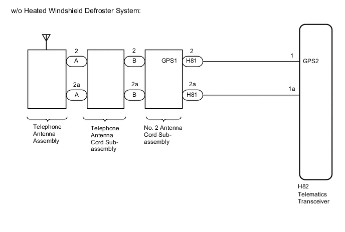
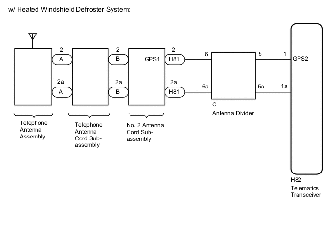
WIRING DIAGRAM
CAUTION / NOTICE / HINT
Note
Depending on the parts that are replaced during vehicle inspection or maintenance, performing initialization, registration or calibration may be needed. Refer to Registration for Telematics System.
PROCEDURE
-
MOVE VEHICLE
-
If the vehicle is outside the communication service area, move the vehicle into a communication service area, wait for a while and perform the operation again.
Result Proceed to NEXT
NEXT 
-
-
CHECK DTC
-
Turn the ignition switch off.
-
Connect the GTS to the DLC3.
-
Turn the ignition switch to ON and wait for 20 seconds.
-
Turn the GTS on.
-
Check for DTCs and check that no DTCs are output.
OK No DTCs are output. Result Proceed to OK NG
OK 
USE SIMULATION METHOD TO CHECK Click here
NG
-
-
CHECK OPTIONAL COMPONENTS
-
Check if any optional components that may decrease reception capacity, such as sunshade film or a telephone antenna, are installed.
Result Result Proceed to Optional components are not installed A Optional components are installed B Note
Do not remove optional components without the permission of the customer.
B
REMOVE OPTIONAL COMPONENTS AND CHECK AGAIN (SEE NOTICE ABOVE)
A
-
-
CHECK DTC OUTPUT
-
Clear the DTCs.
-
Recheck for DTCs and check if the same DTC is output again.
Result Result Proceed to No DTCs are output. A DTC B1583 is output. B
A
USE SIMULATION METHOD TO CHECK Click here
B
-
-
INSPECT TELEPHONE ANTENNA CORD SUB-ASSEMBLY
Result Proceed to OK NG
-
Disconnect the antenna connector from the telephone antenna assembly.
-
Disconnect the antenna connector from the No. 2 antenna cord sub-assembly.
-
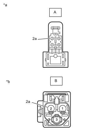
*a Front view of wire harness connector
(to Telephone Antenna Assembly)
*b Front view of wire harness connector
(to No. 2 Antenna Cord Sub-assembly)
Measure the resistance according to the value(s) in the table below.
Standard Resistance Tester Connection Condition Specified Condition A-2 - B-2 Always Below 1 Ω A-2a - B-2a Always Below 1 Ω A-2 - Body ground Always 10 kΩ or higher A-2a - Body ground Always 10 kΩ or higher Result Proceed to OK NG
NG
REPLACE TELEPHONE ANTENNA CORD SUB-ASSEMBLY Click here
OK
-
-
INSPECT NO. 2 ANTENNA CORD SUB-ASSEMBLY
Result Proceed to OK NG
-
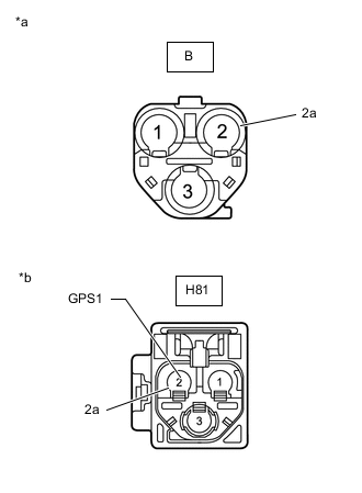
*a Front view of wire harness connector
(to Telephone Antenna Cord Sub-assembly)
*b Front view of wire harness connector
(to Wire Harness)
Disconnect the antenna connector from the telephone antenna cord sub-assembly.
-
Disconnect the antenna connector from the wire harness.
-
Measure the resistance according to the value(s) in the table below.
Standard Resistance Tester Connection Condition Specified Condition B-2 - H81-2 (GPS1) Always Below 1 Ω B-2a - H81-2a Always Below 1 Ω B-2 - Body ground Always 10 kΩ or higher B-2a - Body ground Always 10 kΩ or higher Result Proceed to OK NG
NG
REPLACE NO.2 ANTENNA CORD SUB-ASSEMBLY Click here
OK
-
-
CHECK VEHICLE CONDITION
-
Check the vehicle condition.
Result Result Proceed to w/o Heated Windshield Defroster System A w/ Heated Windshield Defroster System B
B 
CHECK HARNESS AND CONNECTOR (NO. 2 ANTENNA CORD SUB-ASSEMBLY - ANTENNA DIVIDER) Click here
A
-
-
CHECK HARNESS AND CONNECTOR (NO. 2 ANTENNA CORD SUB-ASSEMBLY - TELEMATICS TRANSCEIVER)
Result Proceed to OK NG
-
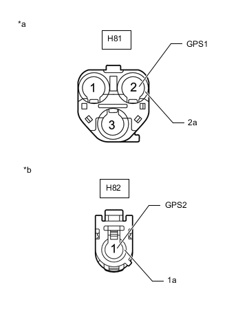
*a Front view of wire harness connector
(to No. 2 Antenna Cord Sub-assembly)
*b Front view of wire harness connector
(to telematics transceiver)
Disconnect the H81 No. 2 antenna cord sub-assembly connector from the instrument panel wire.
-
Disconnect the H82 telematics transceiver connector.
-
Measure the resistance according to the value(s) in the table below.
Standard Resistance Tester Connection Condition Specified Condition H81-2 (GPS1) - H82-1 (GPS2) Always Below 1 Ω H81-2a - H82-1a Always Below 1 Ω H81-2 (GPS1) - Body ground Always 10 kΩ or higher H81-2a - Body ground Always 10 kΩ or higher Result Proceed to OK NG
NG
REPAIR OR REPLACE HARNESS OR CONNECTOR
OK
-
-
CHECK TELEPHONE ANTENNA ASSEMBLY
-
Replace the telephone antenna assembly with a new or known good one.
-
Clear the DTCs.
-
Recheck for DTCs and check that no DTCs are output.
OK No DTCs are output. Result Proceed to OK NG
OK
END (TELEPHONE ANTENNA ASSEMBLY IS DEFECTIVE)
NG
-
-
REPLACE TELEMATICS TRANSCEIVER
-
Replace the telematics transceiver with a new one.
Result Proceed to NEXT
NEXT
PERFORM REGISTRATION Click here
-
-
CHECK HARNESS AND CONNECTOR (NO. 2 ANTENNA CORD SUB-ASSEMBLY - ANTENNA DIVIDER)
Result Proceed to OK NG
-
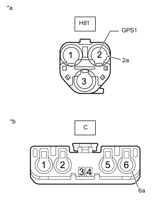
*a Front view of wire harness connector
(to No. 2 Antenna Cord Sub-assembly)
*b Front view of wire harness connector
(to Antenna Divider)
Disconnect the H81 No. 2 antenna cord sub-assembly connector from the wire harness.
-
Disconnect the C Antenna Divider connector.
-
Measure the resistance according to the value(s) in the table below.
Standard Resistance Tester Connection Condition Specified Condition H81-2 (GPS1) - C-6 Always Below 1 Ω H81-2a - C-6a Always Below 1 Ω H81-2 (GPS1) - Body ground Always 10 kΩ or higher H81-2a - Body ground Always 10 kΩ or higher Result Proceed to OK NG
NG
REPAIR OR REPLACE HARNESS OR CONNECTOR
OK
-
-
INSPECT ANTENNA DIVIDER
Result Proceed to OK NG
-
Remove the antenna divider.
-
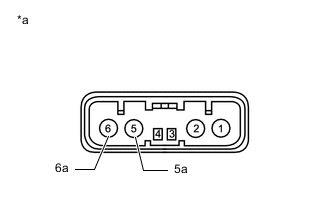
*a Component without harness connected
(Antenna Divider)
Measure the resistance according to the value(s) in the table below.
Standard Resistance Tester Connection Condition Specified Condition 2 - 6 Always 10 kΩ or higher 5 - 6 Always Below 1 Ω 5 - 5a Always 10 kΩ or higher 6 - 6a Always 10 kΩ or higher Result Proceed to OK NG
NG
REPLACE ANTENNA DIVIDER Click here
OK
-
-
CHECK HARNESS AND CONNECTOR (ANTENNA DIVIDER - TELEMATICS TRANSCEIVER)
Result Proceed to OK NG
-
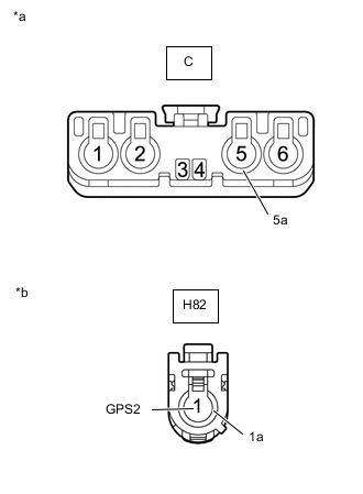
*a Front view of wire harness connector
(to Antenna Divider)
*b Front view of wire harness connector
(to Telematics Transceiver)
Disconnect the C Antenna Divider connector.
-
Disconnect the H82 telematics transceiver connector from the wire harness.
-
Measure the resistance according to the value(s) in the table below.
Standard Resistance Tester Connection Condition Specified Condition C-5 - H82-1 (GPS2) Always Below 1 Ω C-5a - H82-1a Always Below 1 Ω C-5 - Body ground Always 10 kΩ or higher C-5a - Body ground Always 10 kΩ or higher Result Proceed to OK NG
OK
GO TO STEP 9 Click here
NG
REPAIR OR REPLACE HARNESS OR CONNECTOR
-