TOYOTA PARKING ASSIST-SENSOR SYSTEM(w/ Multi-display) SYSTEM DIAGRAM
-
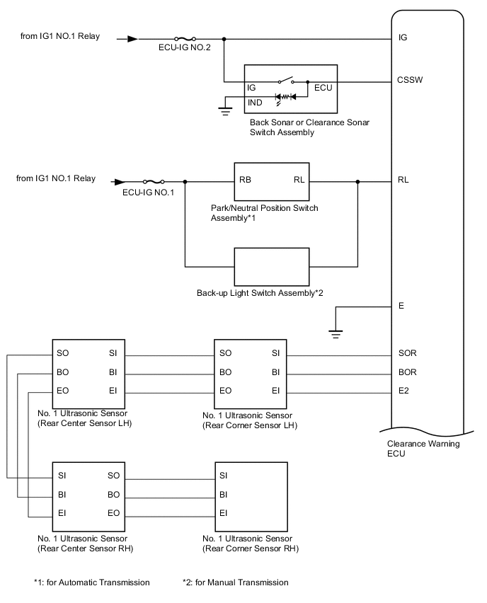
SYSTEM DIAGRAM (for 4 Sensor Type)
-
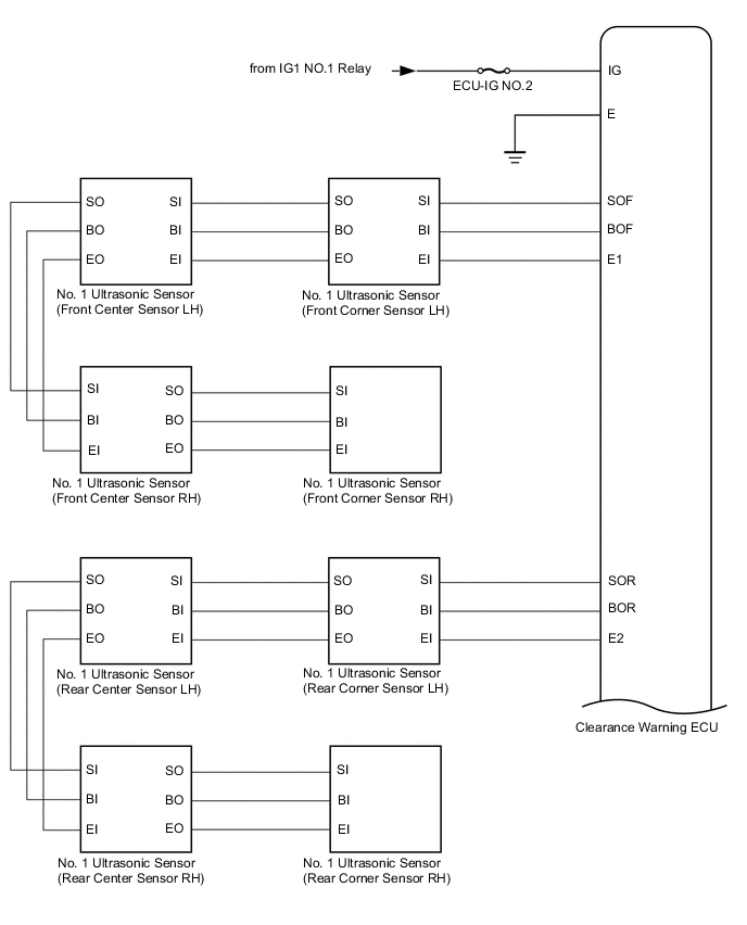
SYSTEM DIAGRAM (for 8 Sensor Type)
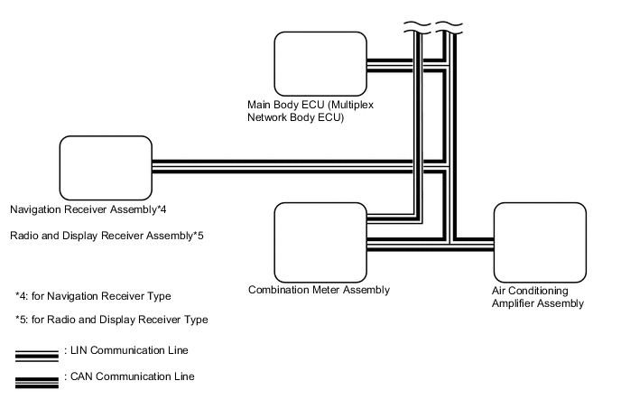
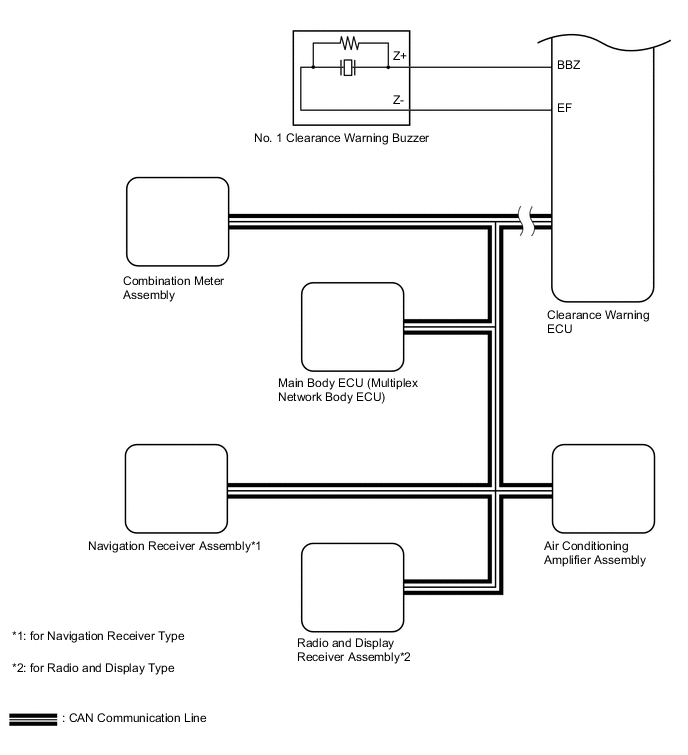
Communication Table Sender Receiver Signal Line Main Body ECU (Multiplex Network Body ECU) Clearance Warning ECU Destination information CAN Combination Meter Assembly Clearance Warning ECU Vehicle speed CAN Air Conditioning Amplifier Assembly Clearance Warning ECU Ambient temperature information CAN Clearance Warning ECU Combination Meter Assembly
-
Clearance sonar indicator illumination request
-
Corner sensor information
-
Front center sensor and rear center sensor information
-
Clearance sonar sensor diagnosis
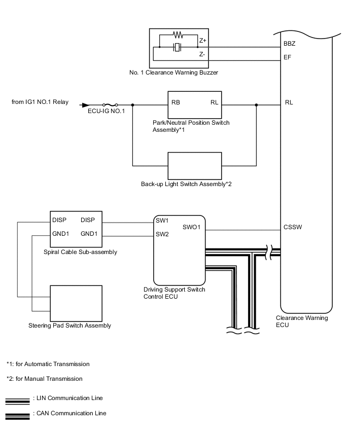
CAN Driving Support Switch Control ECU Combination Meter Assembly Operation information received from the multi-function switch of the steering pad switch assembly which is displayed on the multi-information display in the combination meter assembly LIN Clearance Warning ECU
-
Navigation Receiver Assembly*1
-
Radio and Display Receiver Assembly*2
Display signals from the clearance warning ECU which are displayed on the display panel CAN
-
*1: for Navigation Receiver Type
-
*2: for Radio and Display Type
-