NAVIGATION SYSTEM(for Navigation Receiver Type) Speaker Circuit
DESCRIPTION
The navigation receiver assembly sends sound signals to the speakers.
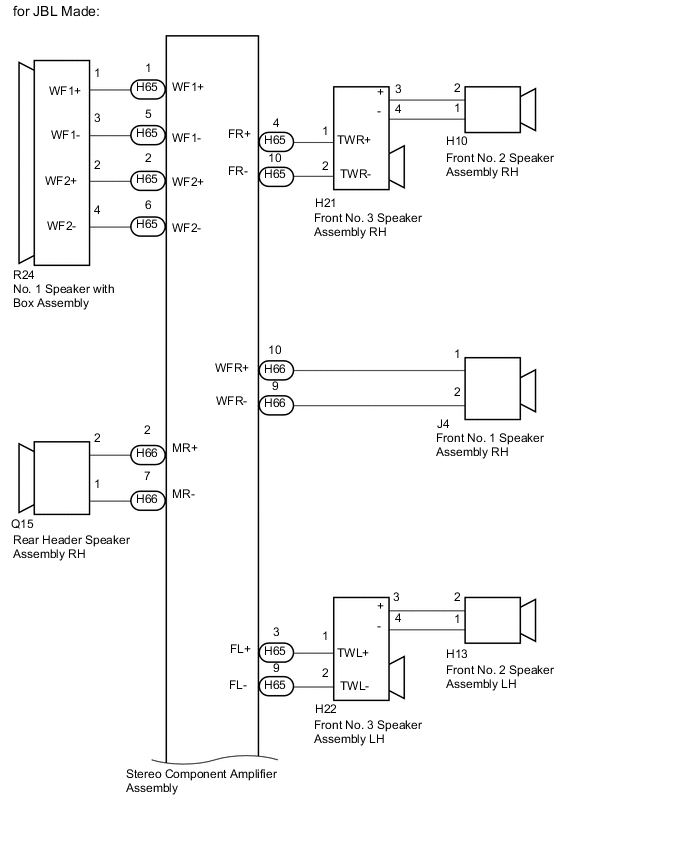
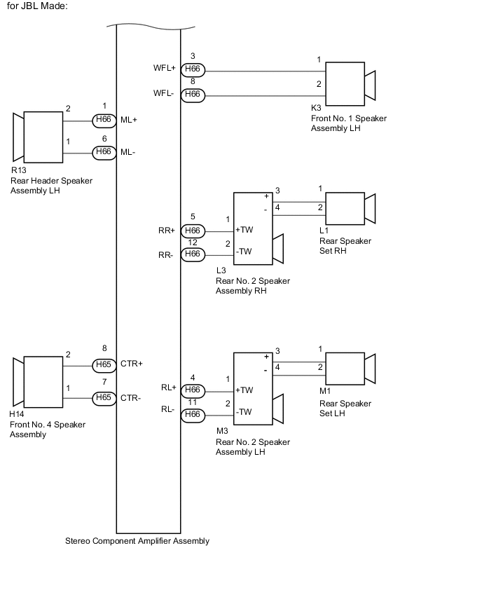
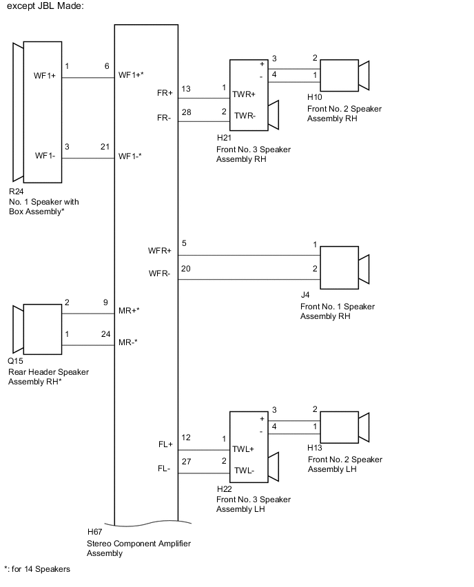
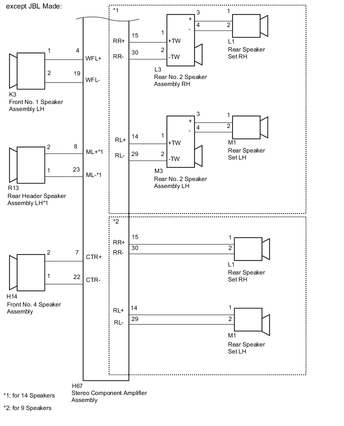
WIRING DIAGRAM
PROCEDURE
-
CHECK VEHICLE CONDITION
-
Check the vehicle condition.
Result Result Proceed to for JBL Made A except JBL Made B
B 
CHECK VEHICLE CONDITION Click here
A 
-
-
CHECK HARNESS AND CONNECTOR (SPEAKER CIRCUIT)
-
*1: for RH Side
-
*2: for LH Side
-
Disconnect the J4*1 and/or K3*2 front No. 1 speaker assembly connector.
-
Disconnect the H10*1 and/or H13*2 front No. 2 speaker assembly connector.
-
Disconnect the H21*1 and/or H22*2 front No. 3 speaker assembly connector.
-
Disconnect the H14 front No. 4 speaker assembly connector.
-
Disconnect the L1*1 and/or M1*2 rear speaker set connector.
-
Disconnect the L3*1 and/or M3*2 rear No. 2 speaker assembly connector.
-
Disconnect the Q15*1 and/or R13*2 rear header speaker assembly connector.
-
Disconnect the R24 No. 1 speaker with box assembly connector.
-
Disconnect the H65 and H66 stereo component amplifier assembly connectors.
-
Measure the resistance according to the value(s) in the table below.
Standard Resistance Tester Connection Condition Specified Condition H65-4 (FR+) - H21-1 (TWR+)*1 Always Below 1 Ω H65-10 (FR-) - H21-2 (TWR-)*1 Always Below 1 Ω H21-3 (+) - H10-2*1 Always Below 1 Ω H21-4 (-) - H10-1*1 Always Below 1 Ω H66-10 (WFR+) - J4-1*1 Always Below 1 Ω H66-9 (WFR-) - J4-2*1 Always Below 1 Ω H65-3 (FL+) - H22-1 (TWL+)*2 Always Below 1 Ω H65-9 (FL-) - H22-2 (TWL-)*2 Always Below 1 Ω H22-3 (+) - H13-2*2 Always Below 1 Ω H22-4 (-) - H13-1*2 Always Below 1 Ω H65-1 (WF1+) - R24-1 (WF1+) Always Below 1 Ω H65-5 (WF1-) - R24-3 (WF1-) Always Below 1 Ω H65-2 (WF2+) - R24-2 (WF2+) Always Below 1 Ω H65-6 (WF2-) - R24-4 (WF2-) Always Below 1 Ω H66-2 (MR+) - Q15-2*1 Always Below 1 Ω H66-7 (MR-) - Q15-1*1 Always Below 1 Ω H66-3 (WFL+) - K3-1*2 Always Below 1 Ω H66-8 (WFL-) - K3-2*2 Always Below 1 Ω H66-5 (RR+) - L3-1 (+TW)*1 Always Below 1 Ω H66-12 (RR-) - L3-2 (-TW)*1 Always Below 1 Ω L3-3 (+) - L1-1*1 Always Below 1 Ω L3-4 (-) - L1-2*1 Always Below 1 Ω H66-4 (RL+) - M3-1 (+TW)*2 Always Below 1 Ω H66-11 (RL-) - M3-2 (-TW)*2 Always Below 1 Ω M3-3 (+) - M1-1*2 Always Below 1 Ω M3-4 (-) - M1-2*2 Always Below 1 Ω H66-1 (ML+) - R13-2*2 Always Below 1 Ω H66-6 (ML-) - R13-1*2 Always Below 1 Ω H65-8 (CTR+) - H14-2 Always Below 1 Ω H66-7 (CTR-) - H14-1 Always Below 1 Ω H65-4 (FR+) - Body ground*1 Always 10 kΩ or higher H65-10 (FR-) - Body ground*1 Always 10 kΩ or higher H21-3 (+) - Body ground*1 Always 10 kΩ or higher H21-4 (-) - Body ground*1 Always 10 kΩ or higher H66-10 (WFR+) - Body ground*1 Always 10 kΩ or higher H66-9 (WFR-) - Body ground*1 Always 10 kΩ or higher H65-3 (FL+) - Body ground*2 Always 10 kΩ or higher H65-9 (FL-) - Body ground*2 Always 10 kΩ or higher H22-3 (+) - Body ground*2 Always 10 kΩ or higher H22-4 (-) - Body ground*2 Always 10 kΩ or higher H65-1 (WF1+) - Body ground Always 10 kΩ or higher H65-5 (WF1-) - Body ground Always 10 kΩ or higher H65-2 (WF2+) - Body ground Always 10 kΩ or higher H65-6 (WF2-) - Body ground Always 10 kΩ or higher H66-2 (MR+) - Body ground*1 Always 10 kΩ or higher H66-7 (MR-) - Body ground*1 Always 10 kΩ or higher H66-3 (WFL+) - Body ground*2 Always 10 kΩ or higher H66-8 (WFL-) - Body ground*2 Always 10 kΩ or higher H66-5 (RR+) - Body ground*1 Always 10 kΩ or higher H66-12 (RR-) - Body ground*1 Always 10 kΩ or higher L3-3 (+) - Body ground*1 Always 10 kΩ or higher L3-4 (-) - Body ground*1 Always 10 kΩ or higher H66-4 (RL+) - Body ground*2 Always 10 kΩ or higher H66-11 (RL-) - Body ground*2 Always 10 kΩ or higher M3-3 (+) - Body ground*2 Always 10 kΩ or higher M3-4 (-) - Body ground*2 Always 10 kΩ or higher H66-1 (ML+) - Body ground*2 Always 10 kΩ or higher H66-6 (ML-) - Body ground*2 Always 10 kΩ or higher H65-8 (CTR+) - Body ground Always 10 kΩ or higher H66-7 (CTR-) - Body ground Always 10 kΩ or higher
NG 
REPAIR OR REPLACE HARNESS OR CONNECTOR
OK
-
-
INSPECT FRONT NO. 1 SPEAKER ASSEMBLY
-
Remove the front No. 1 speaker assembly Click here.
-
Inspect the front No. 1 speaker assembly Click here.
NG
REPLACE FRONT NO. 1 SPEAKER ASSEMBLY Click here
OK
-
-
INSPECT FRONT NO. 2 SPEAKER ASSEMBLY
-
Remove the front No. 2 speaker assembly Click here.
-
Inspect the front No. 2 speaker assembly Click here.
NG
REPLACE FRONT NO. 2 SPEAKER ASSEMBLY Click here
OK
-
-
CHECK FRONT NO. 3 SPEAKER ASSEMBLY
-
Replace the front No. 3 speaker assembly with a known good one Click here.
-
Check that the malfunction disappears.
Note
-
Connect all the connectors that were disconnected to the front No. 3 speaker assemblies.
-
Perform the above inspection on both LH and RH sides.
OK Malfunction disappears. -
OK
END (FRONT NO. 3 SPEAKER ASSEMBLY IS DEFECTIVE)
NG
-
-
CHECK FRONT NO. 4 SPEAKER ASSEMBLY
-
Replace the front No. 4 speaker assembly with a known good one Click here.
-
Check that the malfunction disappears.
OK Malfunction disappears.
OK
END (FRONT NO. 4 SPEAKER ASSEMBLY IS DEFECTIVE)
NG
-
-
INSPECT REAR SPEAKER SET
-
Remove the rear speaker set Click here.
-
Inspect the rear speaker set Click here.
NG
REPLACE REAR SPEAKER SET Click here
OK
-
-
CHECK REAR NO. 2 SPEAKER ASSEMBLY
-
Replace the rear No. 2 speaker assembly with a known good one Click here.
-
Check that the malfunction disappears.
Note
-
Connect all the connectors that were disconnected to the rear No. 2 speaker assemblies.
-
Perform the above inspection on both LH and RH sides.
OK Malfunction disappears. -
OK
END (REAR NO. 2 SPEAKER ASSEMBLY IS DEFECTIVE)
NG
-
-
CHECK REAR HEADER SPEAKER ASSEMBLY
-
Replace the rear header speaker assembly with a known good one Click here.
-
Check that the malfunction disappears.
Note
-
Connect all the connectors that were disconnected to the rear header speaker assemblies.
-
Perform the above inspection on both LH and RH sides.
OK Malfunction disappears. -
OK
END (REAR HEADER SPEAKER ASSEMBLY IS DEFECTIVE)
NG
-
-
INSPECT NO. 1 SPEAKER WITH BOX ASSEMBLY
-
Remove the No. 1 speaker with box assembly Click here.
-
Inspect the No. 1 speaker with box assembly Click here.
NG
REPLACE NO. 1 SPEAKER WITH BOX ASSEMBLY Click here
OK
-
-
CHECK STEREO COMPONENT AMPLIFIER ASSEMBLY
-
Replace the stereo component amplifier assembly with a known good one Click here.
-
Check that the malfunction disappears.
OK Malfunction disappears.
OK
END (STEREO COMPONENT AMPLIFIER ASSEMBLY IS DEFECTIVE)
NG
REPLACE NAVIGATION RECEIVER ASSEMBLY Click here
-
-
CHECK VEHICLE CONDITION
-
Check the vehicle condition.
Result Result Proceed to for 14 Speakers A for 9 Speakers B
B
CHECK HARNESS AND CONNECTOR (SPEAKER CIRCUIT) Click here
A
-
-
CHECK HARNESS AND CONNECTOR (SPEAKER CIRCUIT)
-
*1: for RH Side
-
*2: for LH Side
-
Disconnect the J4*1 and/or K3*2 front No. 1 speaker assembly connector.
-
Disconnect the H10*1 and/or H13*2 front No. 2 speaker assembly connector.
-
Disconnect the H21*1 and/or H22*2 front No. 3 speaker assembly connector.
-
Disconnect the H14 front No. 4 speaker assembly connector.
-
Disconnect the L1*1 and/or M1*2 rear speaker set connector.
-
Disconnect the L3*1 and/or M3*2 rear No. 2 speaker assembly connector.
-
Disconnect the Q15*1 and/or R13*2 rear header speaker assembly connector.
-
Disconnect the R24 No. 1 speaker with box assembly connector.
-
Disconnect the H67 stereo component amplifier assembly connector.
-
Measure the resistance according to the value(s) in the table below.
Standard Resistance Tester Connection Condition Specified Condition H67-13 (FR+) - H21-1 (TWR+)*1 Always Below 1 Ω H67-28 (FR-) - H21-2 (TWR-)*1 Always Below 1 Ω H21-3 (+) - H10-2*1 Always Below 1 Ω H21-4 (-) - H10-1*1 Always Below 1 Ω H67-5 (WFR+) - J4-1*1 Always Below 1 Ω H67-20 (WFR-) - J4-2*1 Always Below 1 Ω H67-12 (FL+) - H22-1 (TWL+)*2 Always Below 1 Ω H67-27 (FL-) - H22-2 (TWL-)*2 Always Below 1 Ω H22-3 (+) - H13-2*2 Always Below 1 Ω H22-4 (-) - H13-1*2 Always Below 1 Ω H67-6 (WF1+) - R24-1 (WF1+) Always Below 1 Ω H67-21 (WF1-) - R24-3 (WF1-) Always Below 1 Ω H67-9 (MR+) - Q15-2*1 Always Below 1 Ω H67-24 (MR-) - Q15-1*1 Always Below 1 Ω H67-4 (WFL+) - K3-1*2 Always Below 1 Ω H67-19 (WFL-) - K3-2*2 Always Below 1 Ω H67-15 (RR+) - L3-1 (+TW)*1 Always Below 1 Ω H67-30 (RR-) - L3-2 (-TW)*1 Always Below 1 Ω L3-3 (+) - L1-1*1 Always Below 1 Ω L3-4 (-) - L1-2*1 Always Below 1 Ω H67-14 (RL+) - M3-1 (+TW)*2 Always Below 1 Ω H67-29 (RL-) - M3-2 (-TW)*2 Always Below 1 Ω M3-3 (+) - M1-1*2 Always Below 1 Ω M3-4 (-) - M1-2*2 Always Below 1 Ω H67-8 (ML+) - R13-2*2 Always Below 1 Ω H67-23 (ML-) - R13-1*2 Always Below 1 Ω H67-7 (CTR+) - H14-2 Always Below 1 Ω H67-22 (CTR-) - H14-1 Always Below 1 Ω H67-13 (FR+) - Body ground*1 Always 10 kΩ or higher H67-28 (FR-) - Body ground*1 Always 10 kΩ or higher H21-3 (+) - Body ground*1 Always 10 kΩ or higher H21-4 (-) - Body ground*1 Always 10 kΩ or higher H67-5 (WFR+) - Body ground*1 Always 10 kΩ or higher H67-20 (WFR-) - Body ground*1 Always 10 kΩ or higher H67-12 (FL+) - Body ground*2 Always 10 kΩ or higher H67-27 (FL-) - Body ground*2 Always 10 kΩ or higher H22-3 (+) - Body ground*2 Always 10 kΩ or higher H22-4 (-) - Body ground*2 Always 10 kΩ or higher H67-6 (WF1+) - Body ground Always 10 kΩ or higher H67-21 (WF1-) - Body ground Always 10 kΩ or higher H67-9 (MR+) - Body ground*1 Always 10 kΩ or higher H67-24 (MR-) - Body ground*1 Always 10 kΩ or higher H67-4 (WFL+) - Body ground*2 Always 10 kΩ or higher H67-19 (WFL-) - Body ground*2 Always 10 kΩ or higher H67-15 (RR+) - Body ground*1 Always 10 kΩ or higher H67-30 (RR-) - Body ground*1 Always 10 kΩ or higher L3-3 (+) - Body ground*1 Always 10 kΩ or higher L3-4 (-) - Body ground*1 Always 10 kΩ or higher H67-14 (RL+) - Body ground*2 Always 10 kΩ or higher H67-29 (RL-) - Body ground*2 Always 10 kΩ or higher M3-3 (+) - Body ground*2 Always 10 kΩ or higher M3-4 (-) - Body ground*2 Always 10 kΩ or higher H67-8 (ML+) - Body ground*2 Always 10 kΩ or higher H67-23 (ML-) - Body ground*2 Always 10 kΩ or higher H67-7 (CTR+) - Body ground Always 10 kΩ or higher H67-22 (CTR-) - Body ground Always 10 kΩ or higher
NG
REPAIR OR REPLACE HARNESS OR CONNECTOR
OK
-
-
INSPECT FRONT NO. 1 SPEAKER ASSEMBLY
-
Remove the front No. 1 speaker assembly Click here.
-
Inspect the front No. 1 speaker assembly Click here.
NG
REPLACE FRONT NO. 1 SPEAKER ASSEMBLY Click here
OK
-
-
INSPECT FRONT NO. 2 SPEAKER ASSEMBLY
-
Remove the front No. 2 speaker assembly Click here.
-
Inspect the front No. 2 speaker assembly Click here.
NG
REPLACE FRONT NO. 2 SPEAKER ASSEMBLY Click here
OK
-
-
CHECK FRONT NO. 3 SPEAKER ASSEMBLY
-
Replace the front No. 3 speaker assembly with a known good one Click here.
-
Check that the malfunction disappears.
Note
-
Connect all the connectors that were disconnected to the front No. 3 speaker assemblies.
-
Perform the above inspection on both LH and RH sides.
OK Malfunction disappears. -
OK
END (FRONT NO. 3 SPEAKER ASSEMBLY IS DEFECTIVE)
NG
-
-
INSPECT FRONT NO. 4 SPEAKER ASSEMBLY
-
Remove the front No. 4 speaker assembly Click here.
-
Inspect the front No. 4 speaker assembly Click here.
NG
REPLACE FRONT NO. 4 SPEAKER ASSEMBLY Click here
OK
-
-
INSPECT REAR SPEAKER SET
-
Remove the rear speaker set Click here.
-
Inspect the rear speaker set Click here.
NG
REPLACE REAR SPEAKER SET Click here
OK
-
-
INSPECT REAR NO. 2 SPEAKER ASSEMBLY
-
Remove the rear No. 2 speaker assembly Click here.
-
Inspect the rear No. 2 speaker assembly Click here.
NG
REPLACE REAR NO. 2 SPEAKER ASSEMBLY Click here
OK
-
-
INSPECT REAR HEADER SPEAKER ASSEMBLY
-
Remove the rear header speaker assembly Click here.
-
Inspect the rear header speaker assembly Click here.
NG
REPLACE REAR HEADER SPEAKER ASSEMBLY Click here
OK
-
-
INSPECT NO. 1 SPEAKER WITH BOX ASSEMBLY
-
Remove the No. 1 speaker with box assembly Click here.
-
Inspect the No. 1 speaker with box assembly Click here.
NG
REPLACE NO. 1 SPEAKER WITH BOX ASSEMBLY Click here
OK
-
-
CHECK STEREO COMPONENT AMPLIFIER ASSEMBLY
-
Replace the stereo component amplifier assembly with a known good one Click here.
-
Check that the malfunction disappears.
OK Malfunction disappears.
OK
END (STEREO COMPONENT AMPLIFIER ASSEMBLY IS DEFECTIVE)
NG
REPLACE NAVIGATION RECEIVER ASSEMBLY Click here
-
-
CHECK HARNESS AND CONNECTOR (SPEAKER CIRCUIT)
-
*1: for RH Side
-
*2: for LH Side
-
Disconnect the J4*1 and/or K3*2 front No. 1 speaker assembly connector.
-
Disconnect the H10*1 and/or H13*2 front No. 2 speaker assembly connector.
-
Disconnect the H21*1 and/or H22*2 front No. 3 speaker assembly connector.
-
Disconnect the H14 front No. 4 speaker assembly connector.
-
Disconnect the L1*1 and/or M1*2 rear speaker set connector.
-
Disconnect the H67 stereo component amplifier assembly connector.
-
Measure the resistance according to the value(s) in the table below.
Standard Resistance Tester Connection Condition Specified Condition H67-13 (FR+) - H21-1 (TWR+)*1 Always Below 1 Ω H67-28 (FR-) - H21-2 (TWR-)*1 Always Below 1 Ω H21-3 (+) - H10-2*1 Always Below 1 Ω H21-4 (-) - H10-1*1 Always Below 1 Ω H67-5 (WFR+) - J4-1*1 Always Below 1 Ω H67-20 (WFR-) - J4-2*1 Always Below 1 Ω H67-12 (FL+) - H22-1 (TWL+)*2 Always Below 1 Ω H67-27 (FL-) - H22-2 (TWL-)*2 Always Below 1 Ω H22-3 (+) - H13-2*2 Always Below 1 Ω H22-4 (-) - H13-1*2 Always Below 1 Ω H67-4 (WFL+) - K3-1*2 Always Below 1 Ω H67-19 (WFL-) - K3-2*2 Always Below 1 Ω H67-15 (RR+) - L1-1*1 Always Below 1 Ω H67-30 (RR-) - L1-2*1 Always Below 1 Ω H67-14 (RL+) - M1-1*2 Always Below 1 Ω H67-29 (RL-) - M1-2*2 Always Below 1 Ω H67-7 (CTR+) - H14-2 Always Below 1 Ω H67-22 (CTR-) - H14-1 Always Below 1 Ω H67-13 (FR+) - Body ground*1 Always 10 kΩ or higher H67-28 (FR-) - Body ground*1 Always 10 kΩ or higher H21-3 (+) - Body ground*1 Always 10 kΩ or higher H21-4 (-) - Body ground*1 Always 10 kΩ or higher H67-5 (WFR+) - Body ground*1 Always 10 kΩ or higher H67-20 (WFR-) - Body ground*1 Always 10 kΩ or higher H67-12 (FL+) - Body ground*2 Always 10 kΩ or higher H67-27 (FL-) - Body ground*2 Always 10 kΩ or higher H22-3 (+) - Body ground*2 Always 10 kΩ or higher H22-4 (-) - Body ground*2 Always 10 kΩ or higher H67-4 (WFL+) - Body ground*2 Always 10 kΩ or higher H67-19 (WFL-) - Body ground*2 Always 10 kΩ or higher H67-15 (RR+) - Body ground*1 Always 10 kΩ or higher H67-30 (RR-) - Body ground*1 Always 10 kΩ or higher H67-14 (RL+) - Body ground*2 Always 10 kΩ or higher H67-29 (RL-) - Body ground*2 Always 10 kΩ or higher H67-7 (CTR+) - Body ground Always 10 kΩ or higher H67-22 (CTR-) - Body ground Always 10 kΩ or higher
NG
REPAIR OR REPLACE HARNESS OR CONNECTOR
OK
-
-
INSPECT FRONT NO. 1 SPEAKER ASSEMBLY
-
Remove the front No. 1 speaker assembly Click here.
-
Inspect the front No. 1 speaker assembly Click here.
NG
REPLACE FRONT NO. 1 SPEAKER ASSEMBLY Click here
OK
-
-
INSPECT FRONT NO. 2 SPEAKER ASSEMBLY
-
Remove the front No. 2 speaker assembly Click here.
-
Inspect the front No. 2 speaker assembly Click here.
NG
REPLACE FRONT NO. 2 SPEAKER ASSEMBLY Click here
OK
-
-
CHECK FRONT NO. 3 SPEAKER ASSEMBL
-
Replace the front No. 3 speaker assembly with a known good one Click here.
-
Check that the malfunction disappears.
Note
-
Connect all the connectors that were disconnected to the front No. 3 speaker assemblies.
-
Perform the above inspection on both LH and RH sides.
OK Malfunction disappears. -
OK
END (FRONT NO. 3 SPEAKER ASSEMBLY IS DEFECTIVE)
NG
-
-
INSPECT FRONT NO. 4 SPEAKER ASSEMBLY
-
Remove the front No. 4 speaker assembly Click here.
-
Inspect the front No. 4 speaker assembly Click here.
NG
REPLACE FRONT NO. 4 SPEAKER ASSEMBLY Click here
OK
-
-
INSPECT REAR SPEAKER SET
-
Remove the rear speaker set Click here.
-
Inspect the rear speaker set Click here.
NG
REPLACE REAR SPEAKER SET Click here
OK
-
-
CHECK STEREO COMPONENT AMPLIFIER ASSEMBLY
-
Replace the stereo component amplifier assembly with a known good one Click here.
-
Check that the malfunction disappears.
OK Malfunction disappears.
OK
END (STEREO COMPONENT AMPLIFIER ASSEMBLY IS DEFECTIVE)
NG
REPLACE NAVIGATION RECEIVER ASSEMBLY Click here
-