NAVIGATION SYSTEM(for Radio and Display Type) Speaker Circuit
DESCRIPTION
If there is a short in a speaker circuit, the stereo component amplifier assembly detects it and stops output to the speakers.
Thus sound cannot be heard from the speakers even if there is no malfunction in the stereo component amplifier assembly, telematics transceiver* or speakers.
*: w/ Telematics Transceiver
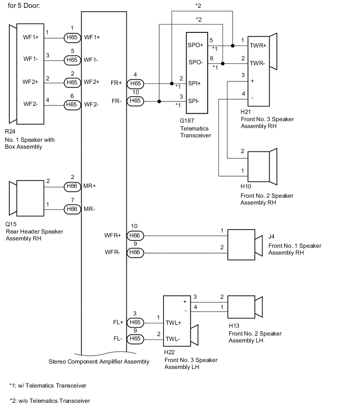
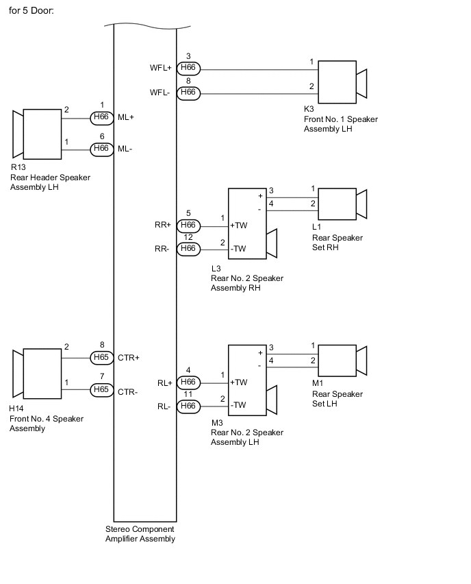
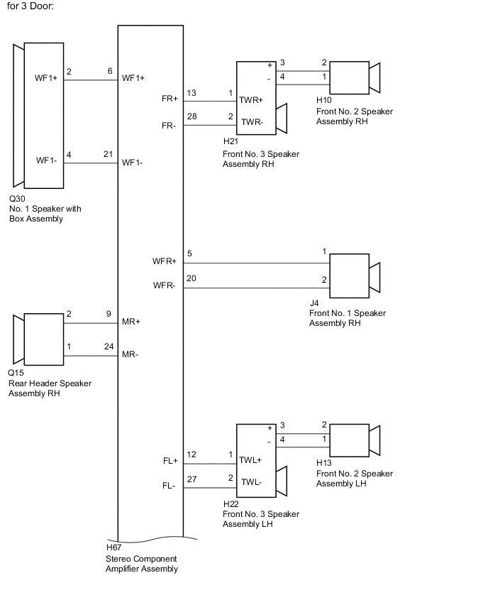
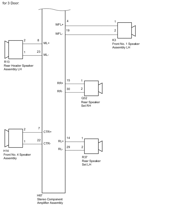
WIRING DIAGRAM
CAUTION / NOTICE / HINT
PROCEDURE
-
CHECK VEHICLE CONDITION
-
Check the vehicle condition.
Result Result Proceed to for 5 Door A for 3 Door B
B 
CHECK HARNESS AND CONNECTOR (SPEAKER CIRCUIT) Click here
A 
-
-
CHECK HARNESS AND CONNECTOR (SPEAKER CIRCUIT)
-
*1: for RH Side
-
*2: for LH Side
-
*3: w/ Telematics Transceiver
-
*4: w/o Telematics Transceiver
-
Disconnect the J4*1 and/or K3*2 front No. 1 speaker assembly connector.
-
Disconnect the H10*1 and/or H13*2 front No. 2 speaker assembly connector.
-
Disconnect the H21*1 and/or H22*2 front No. 3 speaker assembly connector.
-
Disconnect the H14 front No. 4 speaker assembly connector.
-
Disconnect the L1*1 and/or M1*2 rear speaker set connector.
-
Disconnect the L3*1 and/or M3*2 rear No. 2 speaker assembly connector.
-
Disconnect the Q15*1 and/or R13*2 rear header speaker assembly connector.
-
Disconnect the R24 No. 1 speaker with box assembly connector.
-
Disconnect the H65 and H66 stereo component amplifier assembly connectors.
-
Disconnect the G187 telematics transceiver connector.*3
-
Measure the resistance according to the value(s) in the table below.
Standard Resistance for RH Side: Tester Connection Condition Specified Condition H65-4 (FR+) - G187-2 (SPI+)*3 Always Below 1 Ω H65-10 (FR-) - G187-2 (SPI-)*3 Always Below 1 Ω H65-4 (FR+) - H21-1 (TWR+)*4 Always Below 1 Ω H65-10 (FR-) - H21-2 (TWR-)*4 Always Below 1 Ω G187-5 (SPO+) - H21-1 (TWR+)*3 Always Below 1 Ω G187-6 (SPO-) - H21-2 (TWR-)*3 Always Below 1 Ω H21-3 (+) - H10-2 Always Below 1 Ω H21-4 (-) - H10-1 Always Below 1 Ω H66-10 (WFR+) - J4-1 Always Below 1 Ω H66-9 (WFR-) - J4-2 Always Below 1 Ω H66-2 (MR+) - Q15-2 Always Below 1 Ω H66-7 (MR-) - Q15-1 Always Below 1 Ω H66-5 (RR+) - L3-1 (+TW) Always Below 1 Ω H66-12 (RR-) - L3-2 (-TW) Always Below 1 Ω L3-3 (+) - L1-1 Always Below 1 Ω L3-4 (-) - L1-2 Always Below 1 Ω H65-4 (FR+) - Body ground Always 10 kΩ or higher H65-10 (FR-) - Body ground Always 10 kΩ or higher G187-5 (SPO+) - Body ground*3 Always 10 kΩ or higher G187-6 (SPO-) - Body ground*3 Always 10 kΩ or higher H21-3 (+) - Body ground Always 10 kΩ or higher H21-4 (-) - Body ground Always 10 kΩ or higher H66-10 (WFR+) - Body ground Always 10 kΩ or higher H66-9 (WFR-) - Body ground Always 10 kΩ or higher H66-2 (MR+) - Body ground Always 10 kΩ or higher H66-7 (MR-) - Body ground Always 10 kΩ or higher H66-5 (RR+) - Body ground Always 10 kΩ or higher H66-12 (RR-) - Body ground Always 10 kΩ or higher L3-3 (+) - Body ground Always 10 kΩ or higher L3-4 (-) - Body ground Always 10 kΩ or higher Standard Resistance for LH Side: Tester Connection Condition Specified Condition H65-3 (FL+) - H22-1 (TWL+) Always Below 1 Ω H65-9 (FL-) - H22-2 (TWL-) Always Below 1 Ω H22-3 (+) - H13-2 Always Below 1 Ω H22-4 (-) - H13-1 Always Below 1 Ω H66-3 (WFL+) - K3-1 Always Below 1 Ω H66-8 (WFL-) - K3-2 Always Below 1 Ω H66-4 (RL+) - M3-1 (+TW) Always Below 1 Ω H66-11 (RL-) - M3-2 (-TW) Always Below 1 Ω M3-3 (+) - M1-1 Always Below 1 Ω M3-4 (-) - M1-2 Always Below 1 Ω H66-1 (ML+) - R13-2 Always Below 1 Ω H66-6 (ML-) - R13-1 Always Below 1 Ω H65-3 (FL+) - Body ground Always 10 kΩ or higher H65-9 (FL-) - Body ground Always 10 kΩ or higher H22-3 (+) - Body ground Always 10 kΩ or higher H22-4 (-) - Body ground Always 10 kΩ or higher H66-3 (WFL+) - Body ground Always 10 kΩ or higher H66-8 (WFL-) - Body ground Always 10 kΩ or higher H66-4 (RL+) - Body ground Always 10 kΩ or higher H66-11 (RL-) - Body ground Always 10 kΩ or higher M3-3 (+) - Body ground Always 10 kΩ or higher M3-4 (-) - Body ground Always 10 kΩ or higher H66-1 (ML+) - Body ground Always 10 kΩ or higher H66-6 (ML-) - Body ground Always 10 kΩ or higher Standard Resistance for Center Side: Tester Connection Condition Specified Condition H65-1 (WF1+) - R24-1 (WF1+) Always Below 1 Ω H65-5 (WF1-) - R24-3 (WF1-) Always Below 1 Ω H65-2 (WF2+) - R24-2 (WF2+) Always Below 1 Ω H65-6 (WF2-) - R24-4 (WF2-) Always Below 1 Ω H65-8 (CTR+) - H14-2 Always Below 1 Ω H65-7 (CTR-) - H14-1 Always Below 1 Ω H65-1 (WF1+) - Body ground Always 10 kΩ or higher H65-5 (WF1-) - Body ground Always 10 kΩ or higher H65-2 (WF2+) - Body ground Always 10 kΩ or higher H65-6 (WF2-) - Body ground Always 10 kΩ or higher H65-8 (CTR+) - Body ground Always 10 kΩ or higher H65-7 (CTR-) - Body ground Always 10 kΩ or higher Result Proceed to OK NG
NG 
REPAIR OR REPLACE HARNESS OR CONNECTOR
OK
-
-
INSPECT FRONT NO. 1 SPEAKER ASSEMBLY
-
Remove the front No. 1 speaker assembly.
-
Inspect the front No. 1 speaker assembly.
Result Proceed to OK NG
NG
REPLACE FRONT NO. 1 SPEAKER ASSEMBLY Click here
OK
-
-
INSPECT FRONT NO. 2 SPEAKER ASSEMBLY
-
Remove the front No. 2 speaker assembly.
-
Inspect the front No. 2 speaker assembly.
Result Proceed to OK NG
NG
REPLACE FRONT NO. 2 SPEAKER ASSEMBLY Click here
OK
-
-
CHECK FRONT NO. 3 SPEAKER ASSEMBLY
-
Replace the front No. 3 speaker assembly with a known good one.
-
Check that the malfunction disappears.
Note
-
Connect all the connectors that were disconnected to the front No. 3 speaker assemblies.
-
Perform the above inspection on both LH and RH sides.
OK Malfunction disappears. Result Proceed to OK NG (w/ Telematics Transceiver) NG (w/o Telematics Transceiver) -
OK
END (FRONT NO. 3 SPEAKER ASSEMBLY IS DEFECTIVE)
NG (w/o Telematics Transceiver)
GO TO STEP 7 Click here
NG (w/ Telematics Transceiver)
-
-
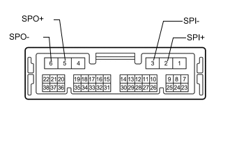
INSPECT TELEMATICS TRANSCEIVER
-
Remove the telematics transceiver.
-
Measure the resistance according to the value(s) in the table below.
Standard Resistance Tester Connection Condition Specified Condition 2 (SPI+) - 5 (SPO+) Always Below 1 Ω 3 (SPI-) - 6 (SPO-) Always Below 1 Ω 2 (SPI+) - Body ground Always 10 kΩ or higher 3 (SPI-) - Body ground Always 10 kΩ or higher Result Proceed to OK NG
NG
REPLACE TELEMATICS TRANSCEIVER Click here
OK
-
-
CHECK FRONT NO. 4 SPEAKER ASSEMBLY
-
Replace the front No. 4 speaker assembly with a known good one.
-
Check that the malfunction disappears.
OK Malfunction disappears. Result Result OK NG
OK
END (FRONT NO. 4 SPEAKER ASSEMBLY IS DEFECTIVE)
NG
-
-
INSPECT REAR SPEAKER SET
-
Remove the rear speaker set.
-
Inspect the rear speaker set.
Result Proceed to OK NG
NG
REPLACE REAR SPEAKER SET Click here
OK
-
-
CHECK REAR NO. 2 SPEAKER ASSEMBLY
-
Replace the rear No. 2 speaker assembly with a known good one.
-
Check that the malfunction disappears.
Note
-
Connect all the connectors that were disconnected to the rear No. 2 speaker assemblies.
-
Perform the above inspection on both LH and RH sides.
OK Malfunction disappears. Result Proceed OK NG -
OK
END (REAR NO. 2 SPEAKER ASSEMBLY IS DEFECTIVE)
NG
-
-
CHECK REAR HEADER SPEAKER ASSEMBLY
-
Replace the rear header speaker assembly with a known good one.
-
Check that the malfunction disappears.
Note
-
Connect all the connectors that were disconnected to the rear header speaker assemblies.
-
Perform the above inspection on both LH and RH sides.
OK Malfunction disappears. Result Proceed OK NG -
OK
END (REAR HEADER SPEAKER ASSEMBLY IS DEFECTIVE)
NG
-
-
INSPECT NO. 1 SPEAKER WITH BOX ASSEMBLY
-
Remove the No. 1 woofer box speaker assembly.
-
Inspect the No. 1 woofer box speaker assembly.
Result Proceed OK NG
NG
REPLACE NO. 1 SPEAKER WITH BOX ASSEMBLY Click here
OK
-
-
CHECK STEREO COMPONENT AMPLIFIER ASSEMBLY
-
Replace the stereo component amplifier assembly with a known good one.
-
Check that the malfunction disappears.
OK Malfunction disappears. Result Proceed OK NG
OK
END (STEREO COMPONENT AMPLIFIER ASSEMBLY IS DEFECTIVE)
NG
REPLACE RADIO & DISPLAY RECEIVER ASSEMBLY Click here
-
-
CHECK HARNESS AND CONNECTOR (SPEAKER CIRCUIT)
-
*1: for RH Side
-
*2: for LH Side
-
Disconnect the J4*1 and/or K3*2 front No. 1 speaker assembly connector.
-
Disconnect the H10*1 and/or H13*2 front No. 2 speaker assembly connector.
-
Disconnect the H21*1 and/or H22*2 front No. 3 speaker assembly connector.
-
Disconnect the H14 front No. 4 speaker assembly connector.
-
Disconnect the Q32*1 and/or R37*2 rear speaker set connector.
-
Disconnect the Q15*1 and/or R13*2 rear header speaker assembly connector.
-
Disconnect the Q30 No. 1 speaker with box assembly connector.
-
Disconnect the H67 stereo component amplifier assembly connector.
-
Measure the resistance according to the value(s) in the table below.
Standard Resistance Tester Connection Condition Specified Condition H67-13 (FR+) - H21-1 (TWR+)*1 Always Below 1 Ω H67-28 (FR-) - H21-2 (TWR-)*1 Always Below 1 Ω H21-3 (+) - H10-2*1 Always Below 1 Ω H21-4 (-) - H10-1*1 Always Below 1 Ω H67-5 (WFR+) - J4-1*1 Always Below 1 Ω H67-20 (WFR-) - J4-2*1 Always Below 1 Ω H67-12 (FL+) - H22-1 (TWL+)*2 Always Below 1 Ω H67-27 (FL-) - H22-2 (TWL-)*2 Always Below 1 Ω H22-3 (+) - H13-2*2 Always Below 1 Ω H22-4 (-) - H13-1*2 Always Below 1 Ω H67-6 (WF1+) - Q30-2 (WF1+) Always Below 1 Ω H67-21 (WF1-) - Q30-4 (WF1-) Always Below 1 Ω H67-9 (MR+) - Q15-2*1 Always Below 1 Ω H67-24 (MR-) - Q15-1*1 Always Below 1 Ω H67-4 (WFL+) - K3-1*2 Always Below 1 Ω H67-19 (WFL-) - K3-2*2 Always Below 1 Ω H67-15 (RR+) - Q32-1*1 Always Below 1 Ω H67-30 (RR-) - Q32-2*1 Always Below 1 Ω H67-14 (RL+) - R37-1*2 Always Below 1 Ω H67-29 (RL-) - R37-2*2 Always Below 1 Ω H67-8 (ML+) - R13-2*2 Always Below 1 Ω H67-23 (ML-) - R13-1*2 Always Below 1 Ω H67-7 (CTR+) - H14-2 Always Below 1 Ω H67-22 (CTR-) - H14-1 Always Below 1 Ω H67-13 (FR+) - Body ground*1 Always 10 kΩ or higher H67-28 (FR-) - Body ground*1 Always 10 kΩ or higher H21-3 (+) - Body ground*1 Always 10 kΩ or higher H21-4 (-) - Body ground*1 Always 10 kΩ or higher H67-5 (WFR+) - Body ground*1 Always 10 kΩ or higher H67-20 (WFR-) - Body ground*1 Always 10 kΩ or higher H67-12 (FL+) - Body ground*2 Always 10 kΩ or higher H67-27 (FL-) - Body ground*2 Always 10 kΩ or higher H22-3 (+) - Body ground*2 Always 10 kΩ or higher H22-4 (-) - Body ground*2 Always 10 kΩ or higher H67-6 (WF1+) - Body ground Always 10 kΩ or higher H67-21 (WF1-) - Body ground Always 10 kΩ or higher H67-9 (MR+) - Body ground*1 Always 10 kΩ or higher H67-24 (MR-) - Body ground*1 Always 10 kΩ or higher H67-4 (WFL+) - Body ground*2 Always 10 kΩ or higher H67-19 (WFL-) - Body ground*2 Always 10 kΩ or higher H67-15 (RR+) - Body ground*1 Always 10 kΩ or higher H67-30 (RR-) - Body ground*1 Always 10 kΩ or higher H67-14 (RL+) - Body ground*2 Always 10 kΩ or higher H67-29 (RL-) - Body ground*2 Always 10 kΩ or higher H67-8 (ML+) - Body ground*2 Always 10 kΩ or higher H67-23 (ML-) - Body ground*2 Always 10 kΩ or higher H67-7 (CTR+) - Body ground Always 10 kΩ or higher H67-22 (CTR-) - Body ground Always 10 kΩ or higher Result Proceed to OK NG
NG
REPAIR OR REPLACE HARNESS OR CONNECTOR
OK
-
-
INSPECT FRONT NO. 1 SPEAKER ASSEMBLY
-
Remove the front No. 1 speaker assembly.
-
Inspect the front No. 1 speaker assembly.
Result Proceed to OK NG
NG
REPLACE FRONT NO. 1 SPEAKER ASSEMBLY Click here
OK
-
-
INSPECT FRONT NO. 2 SPEAKER ASSEMBLY
-
Remove the front No. 2 speaker assembly.
-
Inspect the front No. 2 speaker assembly.
Result Proceed to OK NG
NG
REPLACE FRONT NO. 2 SPEAKER ASSEMBLY Click here
OK
-
-
CHECK FRONT NO. 3 SPEAKER ASSEMBLY
-
Replace the front No. 3 speaker assembly with a known good one.
-
Check that the malfunction disappears.
Note
-
Connect all the connectors that were disconnected to the front No. 3 speaker assemblies.
-
Perform the above inspection on both LH and RH sides.
OK Malfunction disappears. Result Proceed to OK NG -
OK
END (FRONT NO. 3 SPEAKER ASSEMBLY IS DEFECTIVE)
NG
-
-
INSPECT FRONT NO. 4 SPEAKER ASSEMBLY
-
Remove the front No. 4 speaker assembly.
-
Inspect the front No. 4 speaker assembly.
Result Result OK NG
NG
REPLACE FRONT NO. 4 SPEAKER ASSEMBLY Click here
OK
-
-
CHECK REAR SPEAKER SET
-
Remove the rear speaker set.
-
Inspect the rear speaker set with a known good one.
Result Proceed to OK NG
NG
REPLACE REAR SPEAKER SET Click here
OK
-
-
CHECK REAR HEADER SPEAKER ASSEMBLY
-
Remove the rear header speaker assembly.
-
Inspect the rear header speaker assembly.
Result Proceed OK NG
NG
REPLACE REAR HEADER SPEAKER ASSEMBLY Click here
OK
-
-
CHECK NO. 1 SPEAKER WITH BOX ASSEMBLY
-
Remove the No. 1 woofer box speaker assembly.
-
Inspect the No. 1 woofer box speaker assembly.
Result Proceed OK NG
NG
REPLACE NO. 1 SPEAKER WITH BOX ASSEMBLY Click here
OK
-
-
CHECK STEREO COMPONENT AMPLIFIER ASSEMBLY
-
Replace the stereo component amplifier assembly with a known good one.
-
Check that the malfunction disappears.
OK Malfunction disappears. Result Proceed OK NG
OK
END (STEREO COMPONENT AMPLIFIER ASSEMBLY IS DEFECTIVE)
NG
REPLACE RADIO & DISPLAY RECEIVER ASSEMBLY Click here
-