STEREO JACK ADAPTER ASSEMBLY REMOVAL
PROCEDURE
-
PRECAUTION
Note
After turning the ignition switch off, waiting time may be required before disconnecting the cable from the battery terminal. Therefore, make sure to read the disconnecting the cable from the battery terminal notice before proceeding with work.
-
DISCONNECT CABLE FROM NEGATIVE BATTERY TERMINAL
Note
When disconnecting the cable, some systems need to be initialized after the cable is reconnected.
-
REMOVE INSTRUMENT PANEL FINISH PANEL END LH
-
REMOVE INSTRUMENT PANEL FINISH PANEL END RH
-
REMOVE NO. 1 INSTRUMENT PANEL FINISH CUSHION
-
REMOVE NO. 2 INSTRUMENT PANEL FINISH PANEL CUSHION
-
REMOVE LOWER CONSOLE PANEL SUB-ASSEMBLY (w/o Module Switch)
-
REMOVE CENTER INSTRUMENT CLUSTER FINISH PANEL SUB-ASSEMBLY (w/ Module Switch)
-
REMOVE SHIFT LEVER KNOB SUB-ASSEMBLY
Automatic Transmission: Click here
Manual Transmission: Click here
-
REMOVE CONSOLE PANEL SUB-ASSEMBLY (for Automatic Transmission)
-
REMOVE CONSOLE PANEL SUB-ASSEMBLY (for Manual Transmission)
-
REMOVE NO. 1 STEREO JACK ADAPTER ASSEMBLY (for Automatic Transmission)
-
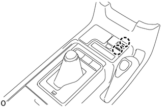
Detach the 2 claws and remove the No. 1 stereo jack adapter assembly.
-
-
REMOVE NO. 1 STEREO JACK ADAPTER ASSEMBLY (for Manual Transmission)
-
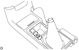
Detach the 2 claws and remove the No. 1 stereo jack adapter assembly.
-
-
REMOVE REAR CONSOLE END PANEL SUB-ASSEMBLY
-
REMOVE VIDEO(VIDEO ADAPTER) TERMINAL
-
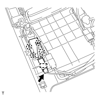
Disconnect the connector.
-
Detach the clamp and 4 claws and remove the video (video adapter) terminal.
-
-
REMOVE HEADPHONE TERMINAL
-
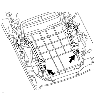
Disconnect the 2 connectors.
-
Detach the 4 claws and 2 clamps and remove the 2 headphone terminals.
-