REAR SEAT ENTERTAINMENT SYSTEM Television Display Power Source Circuit
DESCRIPTION
This is power source circuit of the television display assembly.
WIRING DIAGRAM
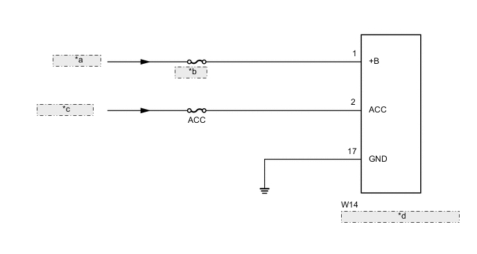
| *a | from Battery |
| *b | RAD NO.3 |
| *c | from ACC Relay |
| *d | Television Display Assembly |
CAUTION / NOTICE / HINT
Note
Inspect the fuses and relays for circuits related to this system before performing the following inspection procedure.
PROCEDURE
-
CHECK HARNESS AND CONNECTOR (TELEVISION DISPLAY ASSEMBLY - BATTERY AND BODY GROUND)
-
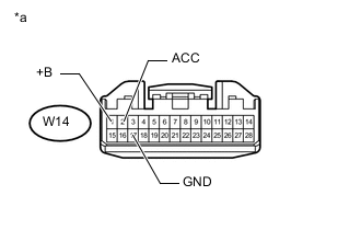
Text in Illustration *a Front view of wire harness connector
(to Television Display Assembly)
Disconnect the television display assembly connector.
-
Measure the resistance according to the value(s) in the table below.
Standard Resistance Tester Connection Condition Specified Condition W14-17 (GND) - Body ground Always Below 1 Ω -
Measure the voltage according to the value(s) in the table below.
Standard Voltage Tester Connection Condition Specified Condition W14-1 (+B) - Body ground Always 11 to 14 V W14-2 (ACC) - Body ground Ignition switch ACC 11 to 14 V
OK 
PROCEED TO NEXT SUSPECTED AREA SHOWN IN PROBLEM SYMPTOMS TABLE Click here
NG
REPAIR OR REPLACE HARNESS OR CONNECTOR
-