REAR SEAT ENTERTAINMENT SYSTEM Display Signal Circuit between Video Terminal and Television Display
DESCRIPTION
This is the display signal from the video (video adapter) terminal to the television display assembly.
WIRING DIAGRAM
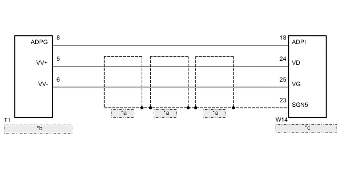
| *a | Shielded |
| *b | Video (VIdeo Adapter) Terminal |
| *c | Television Display Assembly |
PROCEDURE
-
CHECK HARNESS AND CONNECTOR (TELEVISION DISPLAY ASSEMBLY - VIDEO [VIDEO ADAPTER] TERMINAL)
-
Disconnect the W14 television display assembly connector.
-
Disconnect the T1 video (video adapter) terminal connector.
-
Measure the resistance according to the value(s) in the table below.
Standard Resistance Tester Connection Condition Specified Condition W14-18 (ADPI) - T1-8 (ADPG) Always Below 1 Ω W14-24 (VD+) - T1-5 (VV+) Always Below 1 Ω W14-25 (VG) - T1-6 (VV-) Always Below 1 Ω W14-23 (SGN5) - Body ground Always 10 kΩ or higher W14-18 (ADPI) - Body ground Always 10 kΩ or higher W14-24 (VD+) - Body ground Always 10 kΩ or higher W14-25 (VG) - Body ground Always 10 kΩ or higher
NG 
REPAIR OR REPLACE HARNESS OR CONNECTOR
OK 
-
-
CHECK VIDEO (VIDEO ADAPTER) TERMINAL
-
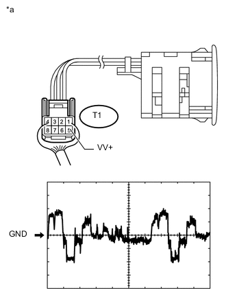
Text in Illustration *a Component with harness connected
(Video [Video Adapter] Terminal)
Remove the video (video adapter) terminal connector still connected Click here.
-
Using an oscilloscope, check the waveform.
Measurement Condition Item Content Terminal No. (Symbol) T1-5 (VV+) - Body ground Tool Setting 0.2 V/DIV., 0.2 μs./DIV. Condition External device playing, VTR displayed OK Waveform is as shown in the illustration.
OK
PROCEED TO NEXT SUSPECTED AREA SHOWN IN PROBLEM SYMPTOMS TABLE Click here
NG
REPLACE VIDEO (VIDEO ADAPTER) TERMINAL Click here
-