AUDIO AND VISUAL SYSTEM(for Radio and Display Type), Diagnostic DTC:B15D3
| DTC Code | DTC Name |
|---|---|
| B15D3 | Stereo Component Amplifier Disconnected |
DESCRIPTION
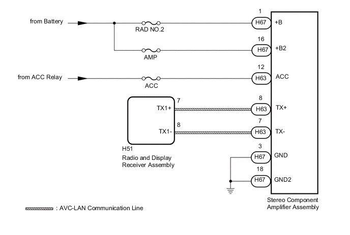
The radio and display receiver assembly and stereo component amplifier assembly are connected by the AVC-LAN communication line.
This DTC is stored when an AVC-LAN communication error occurs between the radio and display receiver assembly.
| DTC Code | DTC Detection Condition | Trouble Area |
|---|---|---|
| B15D3 | When either condition below is met:
|
|
Tech Tips
For the AVC-LAN communication line, the radio and display receiver assembly is the master unit.
WIRING DIAGRAM
CAUTION / NOTICE / HINT
Note
-
If DTC B15C3 is output, perform troubleshooting for DTC B15C3 first Click here.
-
Inspect the fuses for circuits related to this system before performing the following inspection procedure.
Tech Tips
When replacing the radio and display receiver assembly, it is necessary to perform the vehicle contract setting for Connected Services (w/ Connected Services Function).
PROCEDURE
-
CHECK OPTIONAL COMPONENTS (INCLUDING ASSOCIATED WIRING)
-
Check for optional components.
-
Check that optional components (including associated wiring) which generate radio waves are not installed.
Result Result Proceed to Optional components (including associated wiring) are installed. A Optional components (including associated wiring) are not installed. B Tech Tips
-
Electrical noise from radio waves generated by optional components or the wiring for those components may affect AVC-LAN communication.
-
This DTC may be stored when an AVC-LAN communication error occurs due to electrical noise.
-
-
B 
CHECK FOR DTC Click here
A 
-
-
REMOVE OPTIONAL COMPONENTS (INCLUDING ASSOCIATED WIRING)
-
Remove optional components (including associated wiring).
Note
Do not remove optional components or associated wiring without the permission of the customer.
NEXT
-
-
CHECK FOR DTC
-
Clear the DTCs Click here.
-
Check for DTCs Click here.
OK No DTCs are output.
OK 
END (COMMUNICATION MALFUNCTION DUE TO NOISE)
NG
-
-
CHECK HARNESS AND CONNECTOR (STEREO COMPONENT AMPLIFIER ASSEMBLY - BATTERY AND BODY GROUND)
-
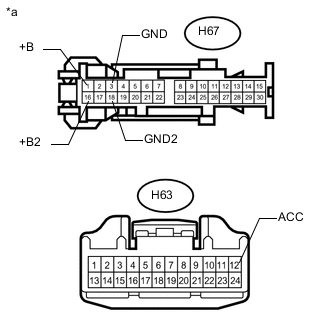
Text in Illustration *a Front view of wire harness connector
(to Stereo Component Amplifier Assembly)
Disconnect the stereo H63 and H67 stereo component amplifier assembly connectors.
-
Measure the resistance according to the value(s) in the table below.
Standard Resistance Tester Connection Condition Specified Condition H67-3 (GND) - Body ground Always Below 1 Ω H67-18 (GND2) - Body ground Always Below 1 Ω -
Measure the voltage according to the value(s) in the table below.
Standard Voltage Tester Connection Condition Specified Condition H67-1 (+B) - H67-3 (GND) Always 11 to 14 V H67-16 (+B2) - H67-3 (GND) Always 11 to 14 V H63-12 (ACC) - H67-3 (GND) Ignition switch ACC 11 to 14 V
NG
REPAIR OR REPLACE HARNESS OR CONNECTOR
OK
-
-
INSPECT RADIO AND DISPLAY RECEIVER ASSEMBLY
-
Remove the radio and display receiver assembly Click here.
-
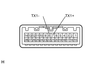
Measure the resistance according to the value(s) in the table below.
Standard Resistance Tester Connection Condition Specified Condition 8 (TX1-) - 7 (TX1+) Always 60 to 80 Ω
NG
REPLACE RADIO AND DISPLAY RECEIVER ASSEMBLY Click here
OK
-
-
CHECK HARNESS AND CONNECTOR (RADIO AND DISPLAY RECEIVER ASSEMBLY - STEREO COMPONENT AMPLIFIER ASSEMBLY)
-
Disconnect the H51 radio and display receiver assembly connector.
-
Disconnect the H67 stereo component amplifier assembly connector.
-
Measure the resistance according to the value(s) in the table below.
Standard Resistance Tester Connection Condition Specified Condition H51-7 (TX1+) - H63-8 (TX+) Always Below 1 Ω H51-8 (TX1-) - H63-7 (TX-) Always Below 1 Ω H51-7 (TX1+) - Body ground Always 10 kΩ or higher H51-8 (TX1-) - Body ground Always 10 kΩ or higher
NG
REPAIR OR REPLACE HARNESS OR CONNECTOR
OK
-
-
CHECK STEREO COMPONENT AMPLIFIER ASSEMBLY
-
Replace the stereo component amplifier assembly with a known good one Click here.
-
Clear the DTCs Click here.
-
Check for DTCs Click here.
OK No DTCs are output.
OK
END (STEREO COMPONENT AMPLIFIER ASSEMBLY IS DEFECTIVE)
NG
REPLACE RADIO AND DISPLAY RECEIVER ASSEMBLY Click here
-