STEERING GEAR REASSEMBLY

PROCEDURE
-
INSTALL STEERING RACK END SUB-ASSEMBLY
-
Temporarily install the 2 steering rack ends to the steering rack.
-
Fill up the ball joints of the steering rack ends with MP grease.
-
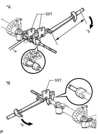
Text in Illustration *A LH Side *B RH Side *a Hold *b Turn Using SST, install the steering rack end (RH side) to the steering rack.
- SST
- 09922-10010
- Torque:
- without SST
- 105 N*m { 1071 kgf*cm, 77 ft.*lbf }
- with SST
- 77 N*m { 784 kgf*cm, 57 ft.*lbf }
Tech Tips
-
Rotate SST in the direction shown in the illustration.
-
Use a torque wrench with a fulcrum length of 400 mm (15.7 in.).
-
Using SST and a wrench, install the steering rack end (LH side) to the steering rack.
- SST
- 09922-10010
- Torque:
- without SST
- 105 N*m { 1071 kgf*cm, 77 ft.*lbf }
- with SST
- 77 N*m { 784 kgf*cm, 57 ft.*lbf }
Tech Tips
-
Rotate SST in the direction shown in the illustration.
-
Use a torque wrench with a fulcrum length of 400 mm (15.7 in.).
-
-
INSTALL NO. 2 STEERING RACK BOOT
-
Apply silicon grease to the inside of the small opening of the boot.
-
Install the 2 boots to the groove on the rack housing.
-
-
INSTALL NO. 1 STEERING RACK BOOT
Tech Tips
Use the same procedures described for the No. 2 boot.
-
INSTALL STEERING RACK BOOT CLAMP RH
-
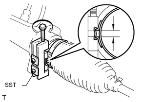
Using SST, install a new boot clamp as shown in the illustration.
- SST
- 09521-24010
Standard clearance 3.0 mm (0.118 in.) or less Note
Be careful not to damage the boot.
-
-
INSTALL STEERING RACK BOOT CLAMP LH
Tech Tips
Use the same procedures described for the RH side.
-
INSTALL STEERING RACK BOOT CLIP RH
-
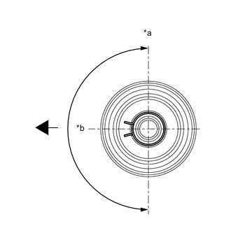
Text in Illustration *a Upward *b 180° 
Front of Vehicle Using pliers, install the boot clip.
Note
Make sure that the claws of the clip are positioned within the area shown in the illustration.
-
-
INSTALL STEERING RACK BOOT CLIP LH
Tech Tips
Use the same procedures described for the RH side.
-
INSTALL STEERING GEAR OUTLET RETURN TUBE
-
Using a union nut wrench, install the return tube to the steering gear.
- Torque:
- 25 N*m { 255 kgf*cm, 18 ft.*lbf }
Tech Tips
Use the formula to calculate special torque values for situations where a union nut wrench is combined with a torque wrench Click here.
-
-
INSTALL TURN PRESSURE TUBE
-
Apply steering fluid to 2 new O-rings. Using a union nut wrench, install the 2 O-rings and turn pressure tube LH.
- Torque:
- 13 N*m { 127 kgf*cm, 9 ft.*lbf }
Tech Tips
Use the formula to calculate special torque values for situations where a union nut wrench is combined with a torque wrench Click here.
-
Apply steering fluid to 2 new O-rings. Using a union nut wrench, install the 2 O-rings and turn pressure tube RH.
- Torque:
- 13 N*m { 127 kgf*cm, 9 ft.*lbf }
Tech Tips
Use the formula to calculate special torque values for situations where a union nut wrench is combined with a torque wrench Click here.
-
-
INSTALL TIE ROD END SUB-ASSEMBLY LH
-
Align the matchmarks of the tie rod and rack end, and temporarily install the tie rod with the lock nut.
Tech Tips
After adjusting toe-in, tighten the lock nut.
- Torque:
- 88 N*m { 897 kgf*cm, 65 ft.*lbf }
-
-
INSTALL TIE ROD END SUB-ASSEMBLY RH
Tech Tips
Use the same procedures described for the LH side.