STEERING HEATER SWITCH INSPECTION
PROCEDURE
-
INSPECT STEERING HEATER SWITCH
-
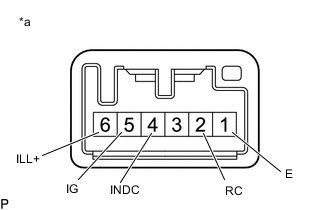
*a Component without harness connected
(Steering Heater Switch)
Measure the voltage according to the value (s) in the table below.
Standard Voltage Tester Connection (Positive (+) Tester Probe - Negative (-) Tester Probe) Switch Condition Specified Condition 5 (IG) - 4 (INDC) Always Below 1.25 V 2 (RC) - 4 (INDC) Steering heater switch is pushed Below 1.25 V Tech Tips
As the circuit has a diode, perform the measurement in diode test mode, and do not mistake the polarity.
-
Measure the resistance according to the value(s) in the table below.
Standard Resistance Tester Connection Switch Condition Specified Condition 5 (IG) - 2 (RC) Pressed Below 1 Ω Not pressed 10 kΩ or higher If the result is not as specified, replace the steering heater switch.
-
Check the illumination.
-
Apply battery voltage between the terminals of the switch, and check the illumination condition of the steering heater switch.
Standard Resistance Measurement Condition Specified Condition Battery positive (+) → A6 (ILL+) Battery negative (-) → A1 (E) Illuminates
-
-