AUDIO AND VISUAL SYSTEM(for Radio Receiver Type) TERMINALS OF ECU
-
CHECK RADIO RECEIVER ASSEMBLY
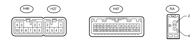
Terminal No. (Symbol) Wiring Color Terminal Description Condition Specified Condition H46-1 (FR+) - H46-7 (GND1) LG - BR Sound signal (Front right) Audio system playing A waveform synchronized with sound signals is output H46-2 (FL+) - H46-7 (GND1) P - BR Sound signal (Front left) Audio system playing A waveform synchronized with sound signals is output H46-3 (ACC1) - H46-7 (GND1) GR - BR ACC signal Ignition switch off Below 1 V Ignition switch ACC 11 to 14 V H46-4 (+B1) - H46-7 (GND1) R - BR Battery Always 11 to 14 V H46-5 (FR-) - H46-7 (GND1) L - BR Sound signal (Front right) Audio system playing A waveform synchronized with sound signals is output H46-6 (FL-) - H46-7 (GND1) V - BR Sound signal (Front left) Audio system playing A waveform synchronized with sound signals is output H46-7 (GND1) - Body ground BR - Body ground Ground Always Below 1 Ω H46-10 (ILL+) - H46-7 (GND1) G - BR Illumination signal Headlight dimmer switch assembly off Below 1 V Headlight dimmer switch assembly tail or head position 11 to 14 V H27-1 (RR+) - H46-7 (GND1) R - BR Sound signal (Rear right) Audio system playing A waveform synchronized with sound signals is output H27-2 (RL+) - H46-7 (GND1) B - BR Sound signal (Rear left) Audio system playing A waveform synchronized with sound signals is output H27-3 (RR-) - H46-7 (GND1) W - BR Sound signal (Rear right) Audio system playing A waveform synchronized with sound signals is output H27-6 (RL-) - H46-7 (GND1) Y - BR Sound signal (Rear left) Audio system playing A waveform synchronized with sound signals is output H47-4 (MACC) - H47-6 (SNS2) R - GR Telephone microphone assembly power supply Ignition switch off Below 1 V Ignition switch ON 4 to 6 V H47-5 (MIN+) - H47-6 (SNS2) B - GR Telephone microphone assembly voice signal "Bluetooth" hands-free function on A waveform synchronized with sound signals is output H47-6 (SNS2) - Body ground GR - Body ground Telephone microphone assembly detected signal Always Below 1 Ω H47-17 (SPD) - H46-7 (GND1) R - BR Speed signal from combination meter Ignition switch ON, drive wheels turned slowly Pulse generation H47-18 (SGND) - Body ground Shielded - Body ground Shield ground Always Below 1 Ω H47-19 (MIN-) - H47-6 (SNS2) W - GR Telephone microphone assembly voice signal "Bluetooth" hands-free function on A waveform synchronized with sound signals is output H47-21 (SW1) - H46-7 (GND1) W - BR Steering pad switch signal No switch pushed 2.8 to 3.57 V Seek+ switch pushed 0 to 0.6 V Seek- switch pushed 0.6 to 1.3 V Volume+ switch pushed 1.3 to 2.1 V Volume- switch pushed 2.1 to 2.8 V H47-22 (SW2) - H46-7 (GND1) B - BR Steering pad switch signal No switch pushed 2.8 to 3.59 V MODE switch pushed 0 to 0.6 V On hook switch pushed 0.6 to 1.3 V Off hook switch pushed 1.3 to 2.1 V H47-23 (SWG) - H46-7 (GND1) W-B - BR Steering pad switch ground Always Below 1 Ω RA-3 (RMAIN) - - - - RA-4 (GND) - Ground - - RA-5 (ANT+) - H46-7 (GND1) # - BR Power source of antenna Ignition switch ACC, radio switch on and AM or FM selected 11 to 14 V
-
#: There is no wire color information.
-