STEERING WHEEL INSPECTION

PROCEDURE
-
INSPECT STEERING PAD SWITCH ASSEMBLY
-
Measure the resistance according to the value(s) in the table below.
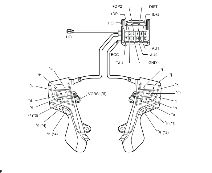
Text in Illustration *1 with ACC switch *2 with LDA switch *3 with Voice switch *4 w/ Hook Switch *5 with VGRS - - *a Seek+ Switch *b Seek- Switch *c Volume+ Switch *d Volume- Switch *e MODE Switch *f Voice Switch *g Off Hook Switch *h On Hook Switch *i LEFT *j RIGHT *k UP *l DOWN *m ENTER *n BACK *o TOP *p ACC *q LDA - - Standard Resistance Tester Connection Switch Condition Specified Condition 11 (AU1) - 8 (EAU) No switch is pushed 95 to 105 kΩ Seek+ switch pushed Below 2.5 Ω Seek- switch pushed 313 to 345 Ω Volume+ switch pushed 950 to 1050 Ω Volume- switch pushed 2955 to 3265 Ω 10 (AU2) - 8 (EAU) No switch is pushed 95 to 105 kΩ Mode switch pushed Below 2.5 Ω Voice switch pushed 2955 to 3265 Ω On Hook switch pushed 313 to 345 Ω Off Hook switch pushed 950 to 1050 Ω 2 (+DP) - 8 (EAU) No switch is pushed 95 to 105 kΩ Left switch pushed Below 2.5 Ω Right switch pushed 2955 to 3265 Ω Up switch pushed 313 to 345 Ω Down switch pushed 950 to 1050 Ω 4 (DIST) - 7 (ECC) No switch is pushed 1MΩ or higher ACC switch pushed Below 2.5 Ω LDA switch pushed 228 to 252 Ω HO - 1 (HO) Always Below 2.5 Ω VGRS - 9 (GND1) Always Below 2.5 Ω If the result is not as specified, replace the steering switch.
-
Connect the battery positive (+) lead to terminal 5 (IL+2) and the negative (-) lead to terminal 8 (EAU) of the steering pad switch connector.
-
Check that the switch illumination comes on.
OK Steering pad switch illumination comes on. If the result is not as specified, replace the steering pad switch.
-
-
INSPECT STEERING PAD SWITCH LH
-
Measure the resistance according to the value(s) in the table below.
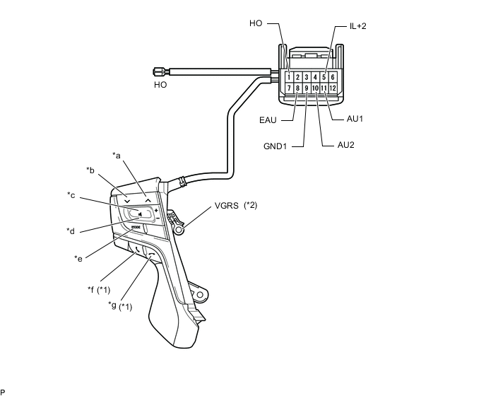
Text in Illustration *1 with Hook Switch *2 with VGRS *a Seek+ Switch *b Seek- Switch *c Volume+ Switch *d Volume- Switch *e MODE Switch *f Off Hook Switch *g On Hook Switch - - Standard Resistance Tester Connection Switch Condition Specified Condition 11 (AU1) - 8 (EAU) No switch is pushed 95 to 105 kΩ Seek+ switch pushed Below 2.5 Ω Seek- switch pushed 313 to 345 Ω Volume+ switch pushed 950 to 1050 Ω Volume- switch pushed 2955 to 3265 Ω 10 (AU2) - 8 (EAU) No switch is pushed 95 to 105 kΩ Mode switch pushed Below 2.5 Ω On Hook switch pushed 313 to 345 Ω Off Hook switch pushed 950 to 1050 Ω HO - 1 (HO) Always Below 2.5 Ω VGRS - 9 (GND1) Always Below 2.5 Ω If the result is not as specified, replace the steering pad switch.
-
Connect the battery positive (+) lead to terminal 5 (IL+2) and the negative (-) lead to terminal 8 (EAU) of the steering pad switch assembly connector.
-
Check that the switch illumination comes on.
OK Steering pad switch illumination comes on. If the result is not as specified, replace the steering pad switch.
-