STEERING COLUMN ASSEMBLY(for Manual Tilt and Manual Telescopic Steering Column) DISASSEMBLY
PROCEDURE
-
REMOVE STEERING LOCK ACTUATOR ASSEMBLY
-
Using a center punch, mark the center of the tapered-head bolt.
-
Using a 3 to 4 mm (0.118 to 0.157 in.) drill, drill a hole in the bolt.
-
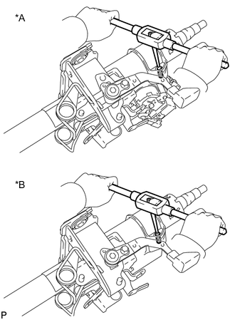
Text in Illustration *A w/o Entry and Start System *B w/ Entry and Start System Using a screw extractor, remove the bolt and steering lock actuator assembly from the steering column assembly.
-
-
REMOVE IGNITION SWITCH LOCK CYLINDER ASSEMBLY (w/o Entry and Start System)
-
Turn the ignition switch to ON (ACC).
-
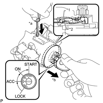
Text in Illustration *1 Claw *2 Stopper *a Push *b Pull Insert the tip of a screwdriver into the hole in the steering column upper bracket, as shown in the illustration, and pull the ignition switch lock cylinder out until its claw comes into contact with the stopper of the steering column upper bracket.
Note
Pull the ignition switch lock cylinder assembly out until its claw comes into contact with the stopper of the steering column bracket assembly upper. Otherwise, the following procedure cannot be conducted properly.
-
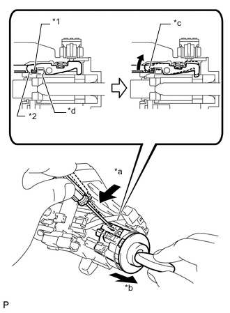
Text in Illustration *1 Stopper *2 Claw *a Tilt *b Pull out *c Claw is disengaged *d Driver insertion hole Insert the tip of a screwdriver into the hole in the steering column bracket and tilt it downward, as shown in the illustration, to disengage the claw of the ignition switch lock cylinder. Then pull out the ignition switch lock cylinder.
-
-
REMOVE UNLOCK WARNING SWITCH ASSEMBLY (w/o Entry and Start System)
-
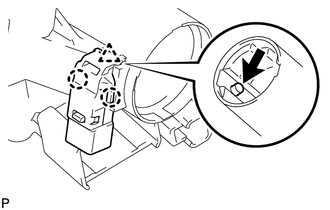
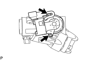
Push up the unlock warning switch center portion to disengage the 2 claws.
Tech Tips
Slide the unlock warning switch in the direction shown by the arrow in the illustration to remove it.
-
-
REMOVE KEY INTERLOCK SOLENOID (w/o Entry and Start System for Automatic Transmission)
-
Disconnect the connector.
-
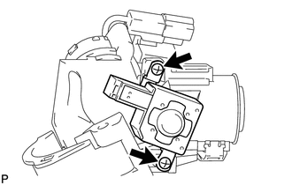
Remove the 2 screws and remove the key interlock solenoid from the steering column upper bracket.
-
-
REMOVE IGNITION SWITCH ASSEMBLY (w/o Entry and Start System)
-
Remove the 2 screws and remove the ignition switch from the steering column upper bracket.
-
-
REMOVE KEY INTERLOCK SOLENOID WIRE (w/o Entry and Start System)
-
Remove the key interlock solenoid wire from the ignition switch.
-