POWER STEERING SYSTEM(w/ VSC) TERMINALS OF ECU
-
CHECK POWER STEERING ECU
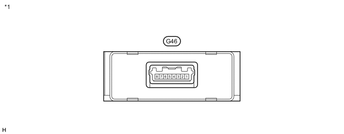
Text in Illustration *1 Power Steering ECU - -
-
Measure the voltage and resistance according to the value(s) in the table below.
Terminal No. (Symbol) Wiring Color Terminal Description Condition Specified Condition G46-3 (GND) - Body ground W-B - Body ground Ground Always Below 1 Ω G46-2 (CANL) - G46-1 (CANH) W - L CAN communication Ignition switch off 54 to 69 Ω G46-5 (IG) - G46-3 (GND) G - W-B IG power supply Ignition switch ON 11 to 14 V G46-7 (SOF+) - G46-8 (SOF-) V - LG Power steering solenoid valve signal
-
Engine idling
-
Steering wheel turned to right or left
Pulse generation If the result is not as specified, the ECU may have a malfunction.
-
-