POWER STEERING SYSTEM(w/ VSC) IG Power Source Circuit
DESCRIPTION
When the ignition switch is turned to ON, the IG power source circuit supplies positive (+) voltage to the power steering ECU.
WIRING DIAGRAM
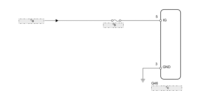
| *a | from IG Circuit |
| *b | ECU-IG NO. 1 |
| *c | Power Steering ECU |
CAUTION / NOTICE / HINT
Note
Inspect the fuses for circuits related to this system before performing the following inspection procedure.
PROCEDURE
-
CHECK HARNESS AND CONNECTOR (POWER STEERING ECU - BATTERY AND BODY GROUND)
-
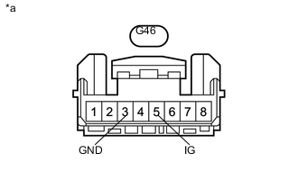
Text in Illustration *a Front view of wire harness connector
(to Power Steering ECU)
Disconnect the power steering ECU connector.
-
Measure the voltage according to the value(s) in the table below.
Standard Voltage Tester Connection Switch Condition Specified Condition G46-5 (IG) - Body ground Ignition switch ON 11 to 14 V -
Measure the resistance according to the value(s) in the table below.
Standard Resistance Tester Connection Condition Specified Condition G46-3 (GND) - Body ground Always Below 1 Ω
OK 
PROCEED TO NEXT SUSPECTED AREA SHOWN IN PROBLEM SYMPTOMS TABLE Click here
NG
REPAIR OR REPLACE HARNESS OR CONNECTOR
-