HYDRAULIC BRAKE BOOSTER(for LHD) INSTALLATION

PROCEDURE
-
INSTALL BRAKE BOOSTER GASKET
-
Install a new brake booster gasket to the hydraulic brake booster.
-
-
INSTALL HYDRAULIC BRAKE BOOSTER ASSEMBLY
-
Install the hydraulic brake booster assembly with the 4 nuts.
- Torque:
- 14 N*m { 145 kgf*cm, 10 ft.*lbf }
-
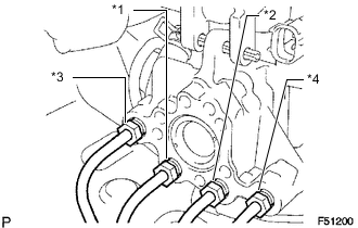
Connect the 4 brake lines to the correct positions of the hydraulic brake booster assembly as shown in the illustration.
Tech Tips
-
*1: To front wheel cylinder RH
-
*2: To front wheel cylinder LH
-
*3: To rear wheel cylinder RH
-
*4: To rear wheel cylinder LH
-
-
Using a union nut wrench, connect the 4 brake lines to the hydraulic brake booster assembly.
- Torque:
- 15 N*m { 155 kgf*cm, 11 ft.*lbf }
Note
Use the formula to calculate special torque values for situations where a union nut wrench is combined with a torque wrench Click here.
-
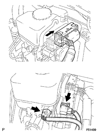
Connect the 3 connectors to the hydraulic brake booster.
-
-
INSTALL PUSH ROD PIN
-
INSTALL LOWER NO. 1 INSTRUMENT PANEL AIRBAG ASSEMBLY
-
Install the lower No. 1 instrument panel airbag assembly Click here.
-
-
CONNECT CABLE TO NEGATIVE BATTERY TERMINAL
Note
When disconnecting the cable, some systems need to be initialized after the cable is reconnected Click here.
-
BLEED BRAKE SYSTEM
-
CHECK AND ADJUST BRAKE PEDAL
-
Check and adjust brake pedal Click here.
-
-
INSPECT BRAKE MASTER CYLINDER OPERATION
-
Inspect the brake master cylinder operation Click here.
-
-
PERFORM YAW RATE AND ACCELERATION SENSOR ZERO POINT CALIBRATION
Note
When replacing the hydraulic brake booster assembly, perform yaw rate and acceleration sensor zero point calibration and acquire information about the following specification as necessary Click here.
-
Downhill assist control calibration
-
Crawl control calibration
-