BRAKE PEDAL(for Vacuum Brake Booster) ON-VEHICLE INSPECTION
PROCEDURE
-
INSPECT BRAKE PEDAL LOAD SENSING SWITCH
Tech Tips
-
Do not remove the brake pedal load sensing switch from the brake pedal lever sub-assembly.
-
When there is a malfunction in the brake pedal load sensing switch, replace the brake pedal lever sub-assembly.
-
The illustration below is for LHD vehicles. Check the brake pedal load sensing switch for RHD vehicles using the same procedure as for LHD vehicles.
-
Disconnect the brake pedal load sensing switch connector.
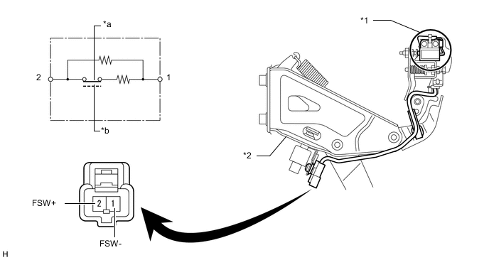
Text in Illustration *1 Brake Pedal Load Sensing Switch *2 Brake Pedal Support Assembly *a Brake Pedal Released (ON) *b Brake Pedal Depressed (OFF) -
Measure the resistance according to the value(s) in the table below.
Standard Resistance Tester Connection Condition Specified Condition 2 (FSW+) - 1(FSW-) Brake pedal depressed 0.9 to 1.1 kΩ Brake pedal released 192 to 234 Ω If the result is not as specified, replace the brake pedal support assembly Click here.
-